Page 207 - Analysis and Design of Machine Elements
P. 207

8.3.2.2  Contact Stress Calculation                             Gear Drives  185
                          During gear mesh, contact points between the engaged teeth move from the tip towards
                          the baseline along tooth profiles. For smooth operation, contact ratio is normally greater
                          than one so that the load is carried by either a single pair or more than one pair of teeth.
                          Therefore, the maximum stress occurs when only a single pair of teeth carries the total
                          load, that is, at points where another pair of teeth is about to pick up its share of load,
                          most probably near the middle of tooth profile, or near pitch point P.
                            Figure 8.4a shows schematically the approximate contact stress distribution along the
                          tooth profile. Since the exact position of point b or c where a single pair of teeth carries
                          the load is difficult to locate precisely; the stress calculation is too complicated at these
                          two points and, also, the actual value of contact stresses at points b, c and P do not vary
                          much; combined with the fact that pitting actually always happens near the pitch line,
                          pitch point P is selected to evaluate contact strength to simplify calculation.
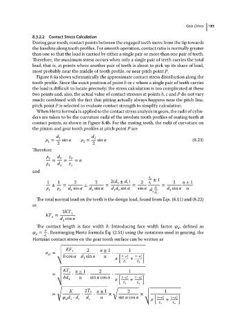
                            When Hertz formula is applied to the contact stress analysis in gears, the radii of cylin-
                          ders are taken to be the curvature radii of the involute tooth profiles of mating teeth at
                          contact points, as shown in Figure 8.4b. For the mating teeth, the radii of curvature on
                          the pinion and gear tooth profiles at pitch point P are
                                    d 1            d 2
                                  =   sin        =   sin                                     (8.23)
                                               2
                                1
                                    2              2
                          Therefore
                                   2  d 2  z 2
                                  =    =    = u
                                   1  d 1  z 1
                          and
                                                                           d 2  ± 1
                                1    1     2        2      2(d ± d )   2   d 1       2   u ± 1
                                                             2
                                                                  1
                                  ±    =        ±        =          =           =
                                   1     2  d sin     d sin     d d sin     sin     d  d 2  d sin     u
                                                   2
                                          1
                                                                                   1
                                                            1 2
                                                                            1
                                                                             d 1
                            The total normal load on the teeth is the design load, found from Eqs. (8.11) and (8.22)
                          as
                                      2KT 1
                               KF =
                                  n
                                      d cos   
                                       1
                            The contact length is face width b. Introducing face width factor    , defined as
                                                                                       d
                               b
                             =  . Rearranging Hertz formula Eq. (2.51) using the notations used in gearing, the
                           d
                               d 1
                          Hertzian contact stress on the gear tooth surface can be written as
                                    √
                                    √
                                    √ KF   t     2    u ± 1       1
                                  =  √       ⋅       ⋅     ⋅  [         ]
                                H
                                    √
                                       b cos     d sin     u      1−   2 1  +  1−   2 2
                                               1
                                                                E 1   E 2
                                    √
                                    √
                                    √KF  t  u ± 1     2           1
                                  =  √     ⋅     ⋅         ⋅  [         ]
                                       bd 1  u    sin    cos         1  +  2
                                    √                          1−   2  1−   2
                                                                E 1   E 2
                                    √
                                                            √            √
                                         K      2T 1  u ± 1       2      √       1
                                  =            ⋅    ⋅     ×            × √ [           ]
                                                                         √
                                          d ⋅ d  d    u       sin    cos      1−    2  1−   2
                                        d 1  1   1                              1  +  2
                                                                               E 1   E 2
   202   203   204   205   206   207   208   209   210   211   212