Page 203 - Analysis and Design of Machine Elements
P. 203

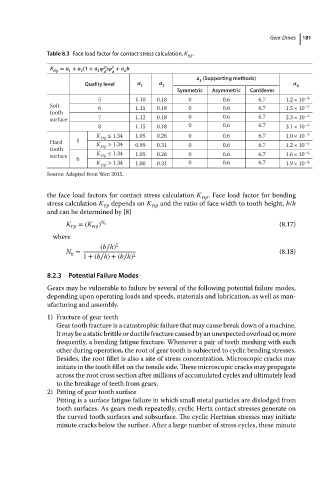
Table 8.3 Face load factor for contact stress calculation, K .  Gear Drives  181
                                                                  H  
                           K  = a + a (1 + a  2 )  2  + a b
                            H   1   2   3  d  d  4
                                                                     a (Supporting methods)
                                                                      3
                                     Quality level  a 1   a 2                                    a 4
                                                               Symmetric  Asymmetric  Cantilever
                                         5         1.10   0.18     0         0.6       6.7     1.2 × 10 −4
                           Soft          6         1.11   0.18     0         0.6       6.7     1.5 × 10 −4
                           tooth                                                                    −4
                           surface       7         1.12   0.18     0         0.6       6.7     2.3 × 10
                                         8         1.15   0.18     0         0.6       6.7     3.1 × 10 −4
                                        K  H  ≤ 1.34  1.05  0.26   0         0.6       6.7     1.0 × 10 −4
                           Hard   5     K  > 1.34  0.99   0.31     0         0.6       6.7     1.2 × 10 −4
                           tooth         H                                                          −4
                           surface      K  H  ≤ 1.34  1.05  0.26   0         0.6       6.7     1.6 × 10
                                  6
                                        K  H  > 1.34  1.00  0.31   0         0.6       6.7     1.9 × 10 −4
                          Source: Adapted from Wen 2015.

                          the face load factors for contact stress calculation K  H   . Face load factor for bending
                          stress calculation K  F    depends on K  H    and the ratio of face width to tooth height, b/h
                          and can be determined by [8]
                               K F    =(K ) N 0                                              (8.17)
                                       H  
                            where
                                         (b∕h) 2
                               N =                                                           (8.18)
                                 0
                                    1 +(b∕h)+(b∕h) 2

                          8.2.3  Potential Failure Modes
                          Gears may be vulnerable to failure by several of the following potential failure modes,
                          depending upon operating loads and speeds, materials and lubrication, as well as man-
                          ufacturing and assembly.
                          1) Fracture of gear teeth
                             Gear tooth fracture is a catastrophic failure that may cause break down of a machine.
                             It may be a static brittle or ductile fracture caused by an unexpected overload or, more
                             frequently, a bending fatigue fracture. Whenever a pair of teeth meshing with each
                             other during operation, the root of gear tooth is subjected to cyclic bending stresses.
                             Besides, the root fillet is also a site of stress concentration. Microscopic cracks may
                             initiate in the tooth fillet on the tensile side. These microscopic cracks may propagate
                             across the root cross section after millions of accumulated cycles and ultimately lead
                             to the breakage of teeth from gears.
                          2) Pitting of gear tooth surface
                             Pitting is a surface fatigue failure in which small metal particles are dislodged from
                             tooth surfaces. As gears mesh repeatedly, cyclic Hertz contact stresses generate on
                             the curved tooth surfaces and subsurface. The cyclic Hertzian stresses may initiate
                             minute cracks below the surface. After a large number of stress cycles, these minute
   198   199   200   201   202   203   204   205   206   207   208