
Page 201 - Analysis and Design of Machine Elements
P. 201
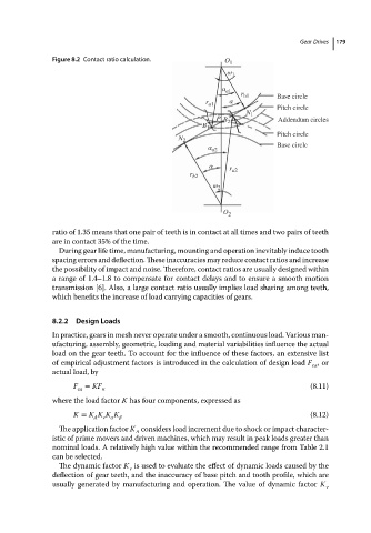
Figure 8.2 Contact ratio calculation.                           Gear Drives  179
                                                                       O 1
                                                                       ω 1
                                                                      α a1
                                                                           r b1     Base circle
                                                                        α
                                                                  r a1
                                                                                    Pitch circle
                                                                            N 1
                                                                     P               Addendum circles
                                                                      B 2
                                                                 B 1
                                                                                    Pitch circle
                                                           N 2
                                                                                    Base circle
                                                                  α a2
                                                                   α
                                                                        r a2
                                                              r b2
                                                                    ω 2


                                                                      O 2

                          ratio of 1.35 means that one pair of teeth is in contact at all times and two pairs of teeth
                          are in contact 35% of the time.
                            During gear life time, manufacturing, mounting and operation inevitably induce tooth
                          spacing errors and deflection. These inaccuracies may reduce contact ratios and increase

                          the possibility of impact and noise. Therefore, contact ratios are usually designed within
                          a range of 1.4–1.8 to compensate for contact delays and to ensure a smooth motion
                          transmission [6]. Also, a large contact ratio usually implies load sharing among teeth,
                          which benefits the increase of load carrying capacities of gears.


                          8.2.2  Design Loads
                          In practice, gears in mesh never operate under a smooth, continuous load. Various man-
                          ufacturing, assembly, geometric, loading and material variabilities influence the actual
                          load on the gear teeth. To account for the influence of these factors, an extensive list
                          of empirical adjustment factors is introduced in the calculation of design load F ,or
                                                                                             ca
                          actual load, by
                               F = KF                                                        (8.11)
                                ca     n
                          where the load factor K has four components, expressed as
                               K = K K K K                                                   (8.12)
                                     A  v
                            The application factor K considers load increment due to shock or impact character-
                                                A
                          istic of prime movers and driven machines, which may result in peak loads greater than
                          nominal loads. A relatively high value within the recommended range from Table 2.1
                          canbeselected.
                            The dynamic factor K is used to evaluate the effect of dynamic loads caused by the
                                              v
                          deflection of gear teeth, and the inaccuracy of base pitch and tooth profile, which are
                          usually generated by manufacturing and operation. The value of dynamic factor K v