
Page 202 - Analysis and Design of Machine Elements
P. 202
Analysis and Design of Machine Elements
180
depends on the accuracy of tooth profile and base pitch, teeth elastic properties and
pitch line velocities, and can be estimated by empirical formula as [3, 7]
( √ ) B
200v
K = 1 + (8.13)
v
A
and
A = 50 + 56(1.0 − B) (8.14)
B = 0.25(12 − Q AGMA ) 0.667 (8.15)
where Q is the gear quality number in the American Gear Manufacturers Asso-
AGMA
ciation (AGMA) standard, ranging from 5 to 11 with increasing precision. Contrary
to the definition in AGMA 2008 standard, gear accuracy grades in ISO, DIN and GB
standards have small numbers to indicate high precision (see Table 8.5). The sum of
the quality number from AGMA 2008 and the corresponding accuracy classification
number from ISO 1328 or AGMA 2015 is always 17 [3]. Therefore, Eq. (8.15) can be
rewritten as
B = 0.25(Q − 5) 0.667 (8.16)
where Q is gear accuracy grade in ISO and GB standards, ranging from 6 to 12.
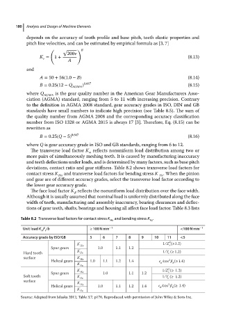
The transverse load factor K reflects nonuniform load distribution among two or
more pairs of simultaneously meshing teeth. It is caused by manufacturing inaccuracy
and teeth deflections under loads, and is determined by many factors, such as base pitch
deviations, contact ratio and gear stiffness. Table 8.2 shows transverse load factors for
contact stress K H and transverse load factors for bending stress K F . When the pinion
and gear are of different accuracy grades, select the transverse load factor according to
the lower gear accuracy grade.
The face load factor K reflects the nonuniform load distribution over the face width.
Although it is usually assumed that nominal load is uniformly distributed along the face
width of teeth, manufacturing and assembly inaccuracy, bearing clearances and deflec-
tions of gear teeth, shafts, bearings and housing all affect face load factor. Table 8.3 lists
Table 8.2 Transverse load factors for contact stress K Ha and bending stress K .
Fa
Unit load K F /b ≥ 100Nmm − 1 <100 N mm − 1
A t
Accuracy grade by ISO/GB 5 6 7 8 9 10 11 <5
2
K H 1 ∕ Z (≥1.2)
Spur gears 1.0 1.1 1.2
K 1∕Y (≥ 1.2)
Hard tooth F
surface K H
Helical gears 1.0 1.1 1.2 1.4 ∕cos 2 (≥1.4)
K b
F
2
K 1∕Z (≥ 1.2)
Spur gears H 1.0 1.1 1.2
Soft tooth K F 1∕Y (≥ 1.2)
surface
K
Helical gears H 1.0 1.1 1.2 1.4 ∕cos 2 b (≥ 1.4)
K F
Source: Adapted from Jelaska 2012, Table 3.7, p176. Reproduced with permission of John Wiley & Sons Inc.