Page 206 - Analysis and Design of Machine Elements
P. 206

Analysis and Design of Machine Elements
                   184
                       8.3.2  Tooth Surface Fatigue Strength Analysis
                       Pitting is a subsurface fatigue phenomenon caused by excessive cyclic contact stresses,
                       resulting in loss of surface materials. Pitting frequently concentrates on a band along
                       the pitch line near dedendum, where high contact stresses occur. Small pinions usu-
                       ally pit first as their teeth experience larger number of stress cycles than teeth on large
                       gears.
                         To resist pitting failure, tooth surface fatigue strength analysis or tooth surface dura-
                       bility analysis is required. The contact stress on the meshing teeth surface is calculated
                       by idealized Hertz contact stress equation, modified by a list of adjustment factors to
                       account for the influence of manufacturing, assembly, geometric, loading and material
                       variabilities. To control pitting, contact stresses should not exceed the allowable contact
                       stress of tooth materials.

                       8.3.2.1  Hertz Formula
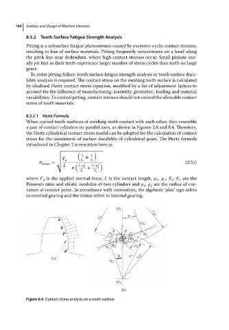
                       When curved tooth surfaces of meshing teeth contact with each other, they resemble
                       a pair of contact cylinders on parallel axes, as shown in Figures 2.8 and 8.4. Therefore,
                       the Hertz cylindrical contact stress model can be adopted for the calculation of contact
                       stress for the assessment of surface durability of cylindrical gears. The Hertz formula
                       introduced in Chapter 2 is rewritten here as
                                    √
                                             (      )
                                    √          1   1
                                    √           ±
                                    √  F         1     2
                                    √ n
                                Hmax  = √  L  ⋅  (  1−   2  1−    2  )                    (2.51)
                                                1  +  2
                                              E 1   E 2
                       where F is the applied normal force, L is the contact length,    ,    , E , E are the
                              n                                               1  2  1   2
                       Poisson’s ratio and elastic modulus of two cylinders and    ,    are the radius of cur-
                                                                         1  2
                       vature at contact point. In accordance with convention, the algebraic ‘plus’ sign refers
                       to external gearing and the minus refers to internal gearing.
                                                             O 2
                                                                  α         r a2
                                     a                r 2
                                                                       r b2
                                      b
                                       P                  ρ 1    P      N 2
                                        c                          B 1
                                                           B 2       ρ 2
                                                         N 1
                                        d
                                                              α    r 1
                                  (a)                                 r a1
                                                          r b1


                                                             O 1
                                                               (b)
                       Figure 8.4 Contact stress analysis on a tooth surface.
   201   202   203   204   205   206   207   208   209   210   211