
Page 209 - Analysis and Design of Machine Elements
P. 209
Gear Drives
of manufacturing, assembly, geometric, loading and material variabilities. To prevent 187
tooth breakage, bending stresses should not exceed the allowable bending stress of gear
materials.
8.3.3.1 Bending Stress Calculation
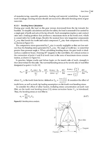
During gear mesh, the load on the gear sweeps downward from the tip towards the
baseline. To simplify calculations and also for safety, the load is assumed to be carried by
a single pair of teeth and acts at the tip of tooth. Such assumption implies a unit contact
ratio and a loading position that produces a maximum stress at the tooth root, which
is conservative for tooth design. Resolve the normal force into tangential components
F cos that bends the tooth and radial component F sin that compresses the tooth,
ca
ca
as showninFigure8.5.
The compressive stress generated by F sin is usually negligible as they are less seri-
ca
ous than the bending stress generated by F cos .Theangle at toothtip is somewhat
ca
greater than pressure angle . When calculating bending stress, the gear tooth is ideal-
∘
ized as a cantilever beam. Drawing 30 tangents to the root fillets, the critical section is
theconnectionofpoint A and B at tooth root in the zone of maximum stress concen-
tration, as shown in Figure 8.5.
In practice, fatigue cracks and failure begin on the tensile side of teeth, strength is
then determined for this side. The nominal bending stress at the tensile side of root fillet
designated as point A is [6, 11]
( )
6cos ⋅ h F
M F cos ⋅ h F KF t 6cos ⋅ h F KF t m KF t
ca
= = = ⋅ = ⋅ = Y
F0 2 2 ( ) 2 Fa
W bs F b cos ⋅ s bm bm
F cos ⋅ s F
6
m
( )
6cos ⋅ h F
where Y Fa is the tooth form factor, defined as Y Fa = ( m ) 2 . It considers the effect of
cos ⋅ s F
m
tooth form, as well as tooth tip loading assumption on the tooth root bending stress.
To consider the effect of other factors, including stress concentration at tooth root
fillet, on the tooth root bending stress [12], stress correction factor Y is introduced.
Sa
Thus, the bending stress at root fillet is
KF t
= Y Y (8.27)
Fa Sa
F
bm
Figure 8.5 Bending stress analysis.
F ca F ca sinγ
γ O
F ca cosγ C
h F
30° 30° Root fillet
A O B
Tangent
s F
Fracture