
Page 222 - Analysis and Design of Machine Elements
P. 222
Analysis and Design of Machine Elements
200
The normal force F canbeobtained from
n
F t1
F = (8.76)
n
cos
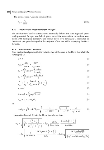
8.5.3 Tooth Surface Fatigue Strength Analysis
The calculation of surface contact stress essentially follows the same approach previ-
ously presented for spur and helical gears, except for some minor corrections asso-
ciated with bevel gear geometry. The contact stress for a bevel gear is calculated on
the virtual spur gear developed at the midpoint of the face width, employing the Hertz
formula.
8.5.3.1 Contact Stress Calculation
For a straight bevel gear tooth, the variables that will be used in the Hertz formula in the
virtual gear are
L = b (a)
KF t1 2KT 1
KF = = (b)
n
cos d m1 cos
d v1 d m1 sin
= sin = (c)
v1
2 2cos 1
d u d sin
= v2 sin = v v1 (d)
v2
2 2
( )
1 1 2cos 1 1
+ = 1 + (e)
d sin u
v1 v2 m1 v
u = u 2 (f)
v
d 1 √
b = R = R 1 + u 2 (g)
R
2
d =(1 − 0.5 )d (h)
m1 R 1
so
√ √
√ 1 1 u
2
cos = 1 − sin = 1 − = 1 − = √ (i)
1
1
2
1 + cot 1 + u 2 2
1 1 + u
Integrating Eqs. (a)–(i) into the Hertz formula, we have
√ √
( ) √ ( )
√ 1 1 1
√ ± √ 2cos 1 +
√ F √ 2KT 1
√ n 1 2 √ 1 u v
H ( 2 2 E
= √ ⋅ ) = Z ⋅
L 1− 1− bd cos d sin
1 + 2 m1 m1
E 1 E 2
√ √
√ ( ) u 1+u 2
√ 2KT cos 1 + 1 √
1
√ 2 1 1 u v √ 2KT √ 1+u 2 u 2
√
= Z E √ ⋅ = Z Z H √ √
E
sin cos bd 2 m1 R 1 + u (1 − 0.5 ) d
2 3
2
2 R 1