
Page 92 - Analysis and Design of Machine Elements
P. 92
Analysis and Design of Machine Elements
70
distributed among all the bolts. Therefore, the external load each bolt subjected to is
F Σ
F = (3.6)
z
The total load a preloaded bolt carries will be discussed in detail in Section 3.5.3.3.
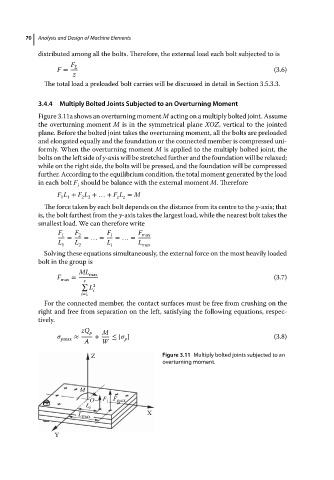
3.4.4 Multiply Bolted Joints Subjected to an Overturning Moment
Figure 3.11a shows an overturning moment M acting on a multiply bolted joint. Assume
the overturning moment M is in the symmetrical plane XOZ, vertical to the jointed
plane. Before the bolted joint takes the overturning moment, all the bolts are preloaded
and elongated equally and the foundation or the connected member is compressed uni-
formly. When the overturning moment M is applied to the multiply bolted joint, the
bolts on the left side of y-axis will be stretched further and the foundation will be relaxed;
while on the right side, the bolts will be pressed, and the foundation will be compressed
further. According to the equilibrium condition, the total moment generated by the load
in each bolt F should be balance with the external moment M. Therefore
i
F L + F L +…+ F L = M
1 1 2 2 z z
The force taken by each bolt depends on the distance from its centre to the y-axis; that
is, the bolt farthest from the y-axis takes the largest load, while the nearest bolt takes the
smallest load. We can therefore write
F 1 F 2 F i F max
= =…= =…=
L 1 L 2 L i L max
Solving these equations simultaneously, the external force on the most heavily loaded
bolt in the group is
ML max
F max = z (3.7)
∑ 2
L
i
i=1
For the connected member, the contact surfaces must be free from crushing on the
right and free from separation on the left, satisfying the following equations, respec-
tively.
zQ p M
≈ + ≤ [ ] (3.8)
pmax p
A W
Z Figure 3.11 Multiply bolted joints subjected to an
overturning moment.
M
O F i F max
L i
X
L max
Y