
Page 89 - Analysis and Design of Machine Elements
P. 89
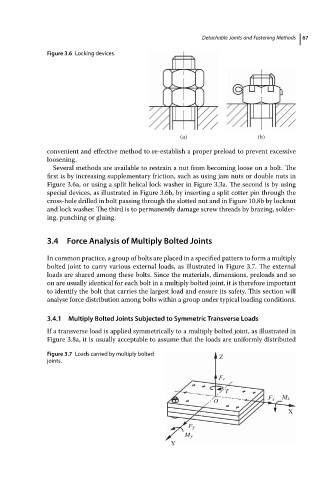
Figure 3.6 Locking devices.                  Detachable Joints and Fastening Methods  67


                                                                (a)                    (b)
                          convenient and effective method to re-establish a proper preload to prevent excessive
                          loosening.
                            Several methods are available to restrain a nut from becoming loose on a bolt. The
                          first is by increasing supplementary friction, such as using jam nuts or double nuts in
                          Figure 3.6a, or using a split helical lock washer in Figure 3.3a. The second is by using
                          special devices, as illustrated in Figure 3.6b, by inserting a split cotter pin through the
                          cross-hole drilled in bolt passing through the slotted nut and in Figure 10.8b by locknut
                          and lock washer. The third is to permanently damage screw threads by brazing, solder-
                          ing, punching or gluing.


                          3.4 Force Analysis of Multiply Bolted Joints
                          In common practice, a group of bolts are placed in a specified pattern to form a multiply
                          bolted joint to carry various external loads, as illustrated in Figure 3.7. The external
                          loads are shared among these bolts. Since the materials, dimensions, preloads and so
                          on are usually identical for each bolt in a multiply bolted joint, it is therefore important
                          to identify the bolt that carries the largest load and ensure its safety. This section will
                          analyse force distribution among bolts within a group under typical loading conditions.

                          3.4.1  Multiply Bolted Joints Subjected to Symmetric Transverse Loads

                          If a transverse load is applied symmetrically to a multiply bolted joint, as illustrated in
                          Figure 3.8a, it is usually acceptable to assume that the loads are uniformly distributed

                          Figure 3.7 Loads carried by multiply bolted       Z
                          joints.

                                                                           Fz
                                                                             T
                                                                          O               Fx  Mx
                                                                                               X

                                                                   Fy
                                                                  My
                                                              Y