
Page 90 - Analysis and Design of Machine Elements
P. 90
Analysis and Design of Machine Elements
68
Z
F ∑ F ∑
2 L min 2
F ∑
O X F ∑ d 0 F ∑ F ∑ d 0 F ∑
F ∑ 2 2
Y
(a) (b) (c)
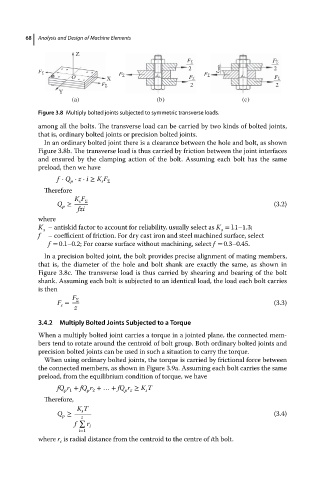
Figure 3.8 Multiply bolted joints subjected to symmetric transverse loads.
among all the bolts. The transverse load can be carried by two kinds of bolted joints,
that is, ordinary bolted joints or precision bolted joints.
In an ordinary bolted joint there is a clearance between the hole and bolt, as shown
Figure 3.8b. The transverse load is thus carried by friction between the joint interfaces
and ensured by the clamping action of the bolt. Assuming each bolt has the same
preload, then we have
f ⋅ Q ⋅ z ⋅ i ≥ K F
p
s Σ
Therefore
K F
s Σ
Q ≥ (3.2)
p
fzi
where
K – antiskid factor to account for reliability, usually select as K = l.1–1.3;
s s
f – coefficient of friction. For dry cast iron and steel machined surface, select
f = 0.1–0.2; For coarse surface without machining, select f = 0.3–0.45.
In a precision bolted joint, the bolt provides precise alignment of mating members,
that is, the diameter of the hole and bolt shank are exactly the same, as shown in
Figure 3.8c. The transverse load is thus carried by shearing and bearing of the bolt
shank. Assuming each bolt is subjected to an identical load, the load each bolt carries
is then
F Σ
F = (3.3)
s
z
3.4.2 Multiply Bolted Joints Subjected to a Torque
When a multiply bolted joint carries a torque in a jointed plane, the connected mem-
bers tend to rotate around the centroid of bolt group. Both ordinary bolted joints and
precision bolted joints can be used in such a situation to carry the torque.
When using ordinary bolted joints, the torque is carried by frictional force between
the connected members, as shown in Figure 3.9a. Assuming each bolt carries the same
preload, from the equilibrium condition of torque, we have
fQ r + fQ r +…+ fQ r ≥ K T
p 1 p 2 p z s
Therefore,
K T
s
Q ≥ (3.4)
p z
∑
f r i
i=1
where r is radial distance from the centroid to the centre of ith bolt.
i