
Page 91 - Analysis and Design of Machine Elements
P. 91
Z
Z Detachable Joints and Fastening Methods 69
fQ p fQ p
F i F max
T r i T r i
r max
O O
X X
Y Y
(a) (b)
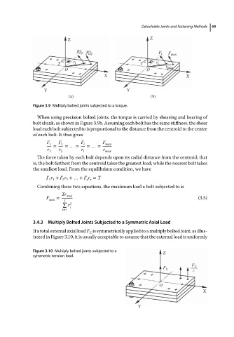
Figure 3.9 Multiply bolted joints subjected to a torque.
When using precision bolted joints, the torque is carried by shearing and bearing of
bolt shank, as shown in Figure 3.9b. Assuming each bolt has the same stiffness, the shear
load each bolt subjected to is proportional to the distance from the centroid to the centre
of each bolt.Itthusgives
F 1 F 2 F i F max
= =…= =…=
r r r r
1 2 i max
The force taken by each bolt depends upon its radial distance from the centroid; that
is, the bolt farthest from the centroid takes the greatest load, while the nearest bolt takes
the smallest load. From the equilibrium condition, we have
F r + F r +…+ F r = T
1 1 2 2 z z
Combining these two equations, the maximum load a bolt subjected to is
Tr max
F max = z (3.5)
∑ 2
r
i
i=1
3.4.3 Multiply Bolted Joints Subjected to a Symmetric Axial Load
If a total external axial load F is symmetrically applied to a multiply bolted joint, as illus-
Σ
trated in Figure 3.10, it is usually acceptable to assume that the external load is uniformly
Figure 3.10 Multiply bolted joints subjected to a Z
symmetric tension load.
F Σ
F Σ
z
O
X
Y