
Page 34 - Analysis, Synthesis and Design of Chemical Processes, Third Edition
P. 34
Both types of block flow diagrams are useful for explaining the overall operation of chemical plants. For
example, consider that you have just joined a large chemical manufacturing company that produces a wide
range of chemical products from the site to which you have been assigned. You would most likely be
given a block flow plant diagram to orient you to the products and important areas of operation. Once
assigned to one of these areas, you would again likely be provided with a block flow process diagram
describing the operations in your particular area.
In addition to the orientation function described earlier, block flow diagrams are used to sketch out and
screen potential process alternatives. Thus, they are used to convey information necessary to make early
comparisons and eliminate competing alternatives without having to make detailed and costly
comparisons.
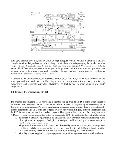
1.2 Process Flow Diagram (PFD)
The process flow diagram (PFD) represents a quantum step up from the BFD in terms of the amount of
information that it contains. The PFD contains the bulk of the chemical engineering data necessary for the
design of a chemical process. For all of the diagrams discussed in this chapter, there are no universally
accepted standards. The PFD from one company will probably contain slightly different information than
the PFD for the same process from another company. Having made this point, it is fair to say that most
PFDs convey very similar information. A typical commercial PFD will contain the following information.
1. All the major pieces of equipment in the process will be represented on the diagram along with a
description of the equipment. Each piece of equipment will have assigned a unique equipment
number and a descriptive name.
2. All process flow streams will be shown and identified by a number. A description of the process
conditions and chemical composition of each stream will be included. These data will be either
displayed directly on the PFD or included in an accompanying flow summary table.
3. All utility streams supplied to major equipment that provides a process function will be shown.