
Page 37 - Analysis, Synthesis and Design of Chemical Processes, Third Edition
P. 37
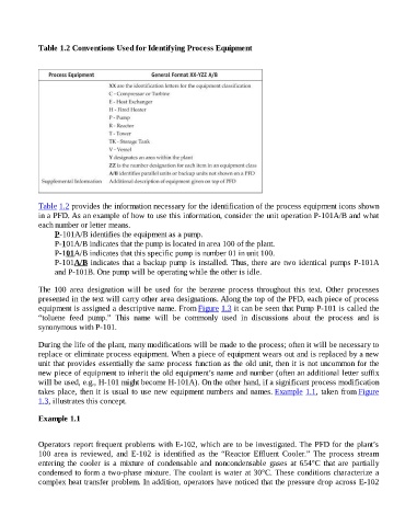
Table 1.2 Conventions Used for Identifying Process Equipment


                    Table 1.2 provides the information necessary for the identification of the process equipment icons shown
                    in a PFD. As an example of how to use this information, consider the unit operation P-101A/B and what
                    each number or letter means.
                          P-101A/B identifies the equipment as a pump.
                          P-101A/B indicates that the pump is located in area 100 of the plant.
                          P-101A/B indicates that this specific pump is number 01 in unit 100.
                          P-101A/B indicates that a backup pump is installed. Thus, there are two identical pumps P-101A
                          and P-101B. One pump will be operating while the other is idle.


                    The  100  area  designation  will  be  used  for  the  benzene  process  throughout  this  text.  Other  processes
                    presented in the text will carry other area designations. Along the top of the PFD, each piece of process
                    equipment is assigned a descriptive name. From Figure 1.3 it can be seen that Pump P-101 is called the
                    “toluene  feed  pump.”  This  name  will  be  commonly  used  in  discussions  about  the  process  and  is
                    synonymous with P-101.


                    During the life of the plant, many modifications will be made to the process; often it will be necessary to
                    replace or eliminate process equipment. When a piece of equipment wears out and is replaced by a new
                    unit that provides essentially the same process function as the old unit, then it is not uncommon for the

                    new piece of equipment to inherit the old equipment’s name and number (often an additional letter suffix
                    will be used, e.g., H-101 might become H-101A). On the other hand, if a significant process modification
                    takes place, then it is usual to use new equipment numbers and names. Example 1.1,  taken  from Figure
                    1.3, illustrates this concept.


                    Example 1.1


                    Operators report frequent problems with E-102, which are to be investigated. The PFD for the plant’s
                    100  area  is  reviewed,  and  E-102  is  identified  as  the  “Reactor  Effluent  Cooler.”  The  process  stream
                    entering  the  cooler  is  a  mixture  of  condensable  and  noncondensable  gases  at  654°C  that  are  partially
                    condensed to form a two-phase mixture. The coolant is water at 30°C. These conditions characterize a

                    complex heat transfer problem. In addition, operators have noticed that the pressure drop across E-102