
Page 41 - Analysis, Synthesis and Design of Chemical Processes, Third Edition
P. 41
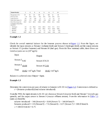
Example 1.2


                    Check  the  overall  material  balance  for  the  benzene  process  shown  in Figure 1.3.  From  the  figure,  we
                    identify the input streams as Stream 1 (toluene feed) and Stream 3 (hydrogen feed) and the output streams
                    as Stream 15 (product benzene) and Stream 16 (fuel gas). From the flow summary table, these flows are
                                                3
                    listed as (units are in (10  kg)/h):

                          Input:
                                                        Output:

                          Stream 3
                                     0.82               Stream 15 8.21

                          Stream 1
                                     10.00              Stream 16 2.61


                          Total
                                                                                3
                                                3
                                     10.82 ×10  kg/h Total          10.82 ×10  kg/h
                    Balance is achieved since Output = Input.


                    Example 1.3


                    Determine the conversion per pass of toluene to benzene in R-101 in Figure 1.3. Conversion is defined as
                          ε = (benzene produced)/(total toluene introduced)

                    From the PFD, the input streams to R-101 are shown as Stream 6 (reactor feed) and Stream 7 (recycle gas

                    quench), and the output stream is Stream 9 (reactor effluent stream). From the information in Table 1.5
                    (units are kmol/h):
                          toluene introduced = 144 (Stream 6) + 0.04 (Stream 7) = 144.04 kmol/h
                          benzene produced = 116 (Stream 9) – 7.6 (Stream 6) – 0.37 (Stream 7) = 108.03 kmol/h
                          ε = 108.03/144.04 = 0.75