
Page 36 - Analysis, Synthesis and Design of Chemical Processes, Third Edition
P. 36
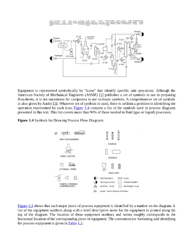
Equipment  is  represented  symbolically  by  “icons”  that  identify  specific  unit  operations. Although  the

                    American Society of Mechanical Engineers (ASME) [2] publishes a set of symbols to use in preparing
                    flowsheets, it is not uncommon for companies to use in-house symbols. A comprehensive set of symbols
                    is also given by Austin [3]. Whatever set of symbols is used, there is seldom a problem in identifying the
                    operation represented by each icon. Figure 1.4 contains a list of the symbols used in process diagrams
                    presented in this text. This list covers more than 90% of those needed in fluid (gas or liquid) processes.


                    Figure 1.4 Symbols for Drawing Process Flow Diagrams


                    Figure 1.3 shows that each major piece of process equipment is identified by a number on the diagram. A
                    list of the equipment numbers along with a brief descriptive name for the equipment is printed along the
                    top  of  the  diagram.  The  location  of  these  equipment  numbers  and  names  roughly  corresponds  to  the
                    horizontal location of the corresponding piece of equipment. The convention for formatting and identifying
                    the process equipment is given in Table 1.2.