
Page 127 - Analytical Electrochemistry 2d Ed - Jospeh Wang
P. 127
112 PRACTICAL CONSIDERATIONS
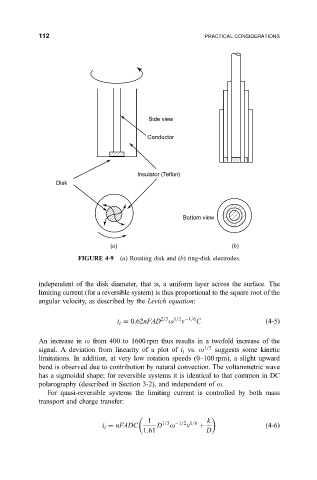
Side view
Conductor
Insulator (Teflon)
Disk
Bottom view
(a) (b)
FIGURE 4-9 (a) Rotating disk and (b) ring-disk electrodes.
independent of the disk diameter, that is, a uniform layer across the surface. The
limiting current (for a reversible system) is thus proportional to the square root of the
angular velocity, as described by the Levich equation:
n
i 0:62nFAD 2=3 o 1=2 1=6 C
4-5
l
An increase in o from 400 to 1600 rpm thus results in a twofold increase of the
signal. A deviation from linearity of a plot of i vs. o 1=2 suggests some kinetic
l
limitations. In addition, at very low rotation speeds (0±100 rpm), a slight upward
bend is observed due to contribution by natural convection. The voltammetric wave
has a sigmoidal shape; for reversible systems it is identical to that common in DC
polarography (described in Section 3-2), and independent of o.
For quasi-reversible systems the limiting current is controlled by both mass
transport and charge transfer:
1 1=3 1=2 1=6 k
i nFADC D o n
4-6
l
1:61 D