
Page 276 - Antennas for Base Stations in Wireless Communications
P. 276
Antennas for WLAN (WiFi) Applications 249
adequate for such applications; instead, patch antenna arrays or reflector
antennas are preferred. The planar patch antenna array has the advantage
of having a low profile and high gain, typically to 12–18 dBi. Reflector
antennas (such as parabolic dishes) and horn antennas are used when the
required gain exceeds 18 dBi, despite having a larger profile and volume.
SS and AP antennas usually provide P2MP links. These antennas
require broad radiation patterns in the plane where there are multiple
terminals for achieving wide coverage. An array of radiating elements is
required to manipulate the radiation patterns. The radiation patterns of
the antenna array can be tailored to achieve a sectored or omnidirectional
coverage based on the systems’ requirements.
7.2.2 MIMO Antenna System
Design Considerations
In a MIMO system, the effect of the antenna on system performance
will be to some degree distinct from conventional WLANs. Such an effect
stems from MIMO system requirements. Therefore, understanding the
features of MIMO systems will be conducive to designing the antennas.
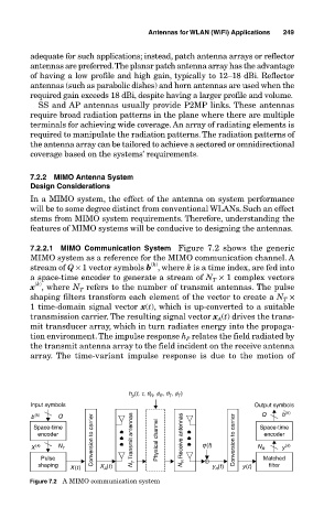
7.2.2.1 MIMO Communication System Figure 7.2 shows the generic
MIMO system as a reference for the MIMO communication channel. A
(k)
stream of Q × 1 vector symbols b , where k is a time index, are fed into
a space-time encoder to generate a stream of N T × 1 complex vectors
(k)
x , where N T refers to the number of transmit antennas. The pulse
shaping filters transform each element of the vector to create a N T ×
1 time-domain signal vector x(t), which is up-converted to a suitable
(t) drives the trans-
transmission carrier. The resulting signal vector x A
mit transducer array, which in turn radiates energy into the propaga-
tion environment. The impulse response h relates the field radiated by
P
the transmit antenna array to the field incident on the receive antenna
array. The time-variant impulse response is due to the motion of
h (t, t, q , f , q , f )
p
R
R
T
T
Input symbols Output symbols
b (k) Q Q b ˆ (k)
Space-time Space-time
encoder encoder
X (k) N T Conversion to carrier N T Transmit antennas Physical channel N R Receive antennas g (t) Conversion to carrier N R y (k)
Pulse Matched
shaping X (t) X A (t) y (t) y(t) filter
A
Figure 7.2 A MIMO communication system