
Page 281 - Antennas for Base Stations in Wireless Communications
P. 281
254 Chapter Seven
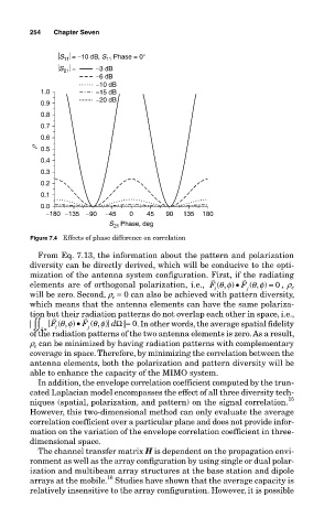
S = −10 dB, S Phase = 0°
11
11
S = −3 dB
21
−6 dB
−10 dB
1.0 −15 dB
0.9 −20 dB
0.8
0.7
0.6
r 0.5
0.4
0.3
0.2
0.1
0.0
−180 −135 −90 −45 0 45 90 135 180
S 21 Phase, deg
Figure 7.4 Effects of phase difference on correlation
From Eq. 7.13, the information about the pattern and polarization
diversity can be directly derived, which will be conducive to the opti-
mization of the antenna system configuration. First, if the radiating
v
v
elements are of orthogonal polarization, i.e., F ( , )θ φ • F ( , )θ φ = 0 , r e
j
i
will be zero. Second, r e = 0 can also be achieved with pattern diversity,
which means that the antenna elements can have the same polariza-
tion but their radiation patterns do not overlap each other in space, i.e.,
v
v
θ
θ
φ
φ
•
F
| ∫∫ [ ( , ) F j ( , )] dΩ |= 0. In other words, the average spatial fidelity
i
4
π
of the radiation patterns of the two antenna elements is zero. As a result,
r can be minimized by having radiation patterns with complementary
e
coverage in space. Therefore, by minimizing the correlation between the
antenna elements, both the polarization and pattern diversity will be
able to enhance the capacity of the MIMO system.
In addition, the envelope correlation coefficient computed by the trun-
cated Laplacian model encompasses the effect of all three diversity tech-
15
niques (spatial, polarization, and pattern) on the signal correlation.
However, this two-dimensional method can only evaluate the average
correlation coefficient over a particular plane and does not provide infor-
mation on the variation of the envelope correlation coefficient in three-
dimensional space.
The channel transfer matrix H is dependent on the propagation envi-
ronment as well as the array configuration by using single or dual polar-
ization and multibeam array structures at the base station and dipole
16
arrays at the mobile. Studies have shown that the average capacity is
relatively insensitive to the array configuration. However, it is possible