
Page 283 - Antennas for Base Stations in Wireless Communications
P. 283
256 Chapter Seven
TABLE 7.2 Various Types of WLAN Antennas in the Market
Gain, dBi
Antennas 0–6 6–8 8–18 18–30
Single monopole
Helix (normal mode)
Single dipole
Slot
Log-periodic
Dipole, slot, patch (arrays)
Yagi-Uda
Horn
Reflector, dish
patch arrays, Yagi-Uda arrays, log-periodic arrays, helix antennas,
cavity-backed slot antennas, waveguide slot arrays, horn antennas, and
reflector antennas. The beamwidth of these antennas is usually between
20°−60° based on the system requirements. A beamwidth of less than
10° requires additional antenna alignment procedures. Also, an antenna
with a high directivity has a lower probability of encountering unpre-
dictable interferences.
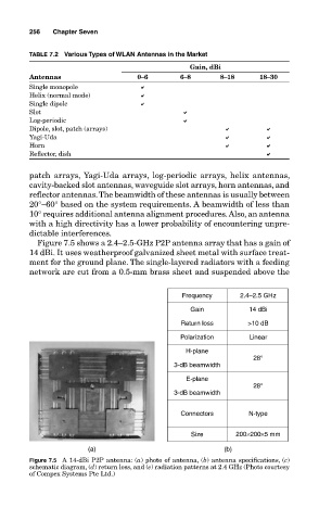
Figure 7.5 shows a 2.4–2.5-GHz P2P antenna array that has a gain of
14 dBi. It uses weatherproof galvanized sheet metal with surface treat-
ment for the ground plane. The single-layered radiators with a feeding
network are cut from a 0.5-mm brass sheet and suspended above the
Frequency 2.4–2.5 GHz
Gain 14 dBi
Return loss >10 dB
Polarization Linear
H-plane
28°
3-dB beamwidth
E-plane
28°
3-dB beamwidth
Connectors N-type
Size 200×200×5 mm
(a) (b)
Figure 7.5 A 14-dBi P2P antenna: (a) photo of antenna, (b) antenna specifications, (c)
schematic diagram, (d) return loss, and (e) radiation patterns at 2.4 GHz (Photo courtesy
of Compex Systems Pte Ltd.)