
Page 285 - Antennas for Base Stations in Wireless Communications
P. 285
258 Chapter Seven
The meandered feeding lines after the T-junctions are designed to
ensure that the signals at the top radiators are equi-amplitude but
180° out-of-phase with respect to the bottom radiators. As a thin mean-
dered line results in a reduction of the bandwidth, whereas a closely
coupled line increases the coupling loss, optimizing the feeding lines
is, therefore, necessary. The patches are separated by approximately
half a wavelength so as to achieve the desired array factor. Grating
lobes occur when the spacing between the patches is greater than one
wavelength, while a separation of less than one quarter wavelength
increases the mutual coupling and reduces the radiation efficiency. The
height of this patch array is only 5 mm (4% of a wavelength); hence, it
is narrowband.
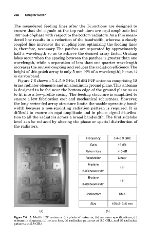
Figure 7.6 shows a 5.4–5.9 GHz, 16 dBi P2P antenna comprising 12
brass radiator elements and an aluminum ground plane. This antenna
is designed to be fed near the bottom edge of the ground plane so as
to fit into a low-profile casing. The feeding structure is simplified to
ensure a low fabrication cost and mechanical robustness. However,
the long series-fed array structure limits the usable operating band-
width because a non-squinting radiation pattern is required. It is
difficult to ensure an equi-amplitude and in-phase signal distribu-
tion to all the radiators across a broad bandwidth. The first sidelobe
level can be reduced by altering the phase or spatial distribution of
the radiators.
Frequency 5.4–5.9 GHz
Gain 16 dBi
Return loss >10 dB
Polarization Linear
H-plane
16°
3-dB beamwidth
E-plane
16°
3-dB beamwidth
Connectors SMA
Size 155×213×5 mm
(a) (b)
Figure 7.6 A 16-dBi P2P antenna: (a) photo of antenna, (b) antenna specifications, (c)
schematic diagram, (d) return loss, (e) radiation patterns at 5.6 GHz, and (f) radiation
patterns at 5.8 GHz