Page 284 - Antennas for Base Stations in Wireless Communications
P. 284

Antennas for WLAN (WiFi) Applications        257


                        11       60          58

                                   25.5
                       51           30
                                    5

                              12        10                  6.5
                  200  57        12
                          14        14                  4       24
                                            108
                            11.5                            17


                                                                      y          y
                        20.5                                              x   z

                                            200
                             0.5   ∅5.5 Nut                        Brass metal plate
                                                                      z
                          1        ∅2.0 Screw   ∅2.9  5
                                                N-type connector          x
                                                                             Unit: mm
                                                   (c)
                                                              q = 0°    E-plane, Co-pol
                       0                                                H-plane, Co-pol
                                                                        2.4 GHz
                      −5
                    |S 11 |, dB  −10               −90°                   90°


                     −15                                        0
                                                                10
                     −20
                        2.2 2.3  2.4  2.5  2.6  2.7  2.8
                               Frequency, GHz                  180° (20 dBi)
                                    (d)                        (e)
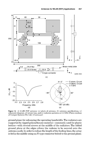
                  Figure 7.5  A 14-dBi P2P antenna: (a) photo of antenna, (b) antenna specifications, (c)
                  schematic diagram, (d) return loss, and (e) radiation patterns at 2.4 GHz (Photo courtesy
                  of Compex Systems Pte Ltd.) (Continued)
                  ground plane for enhancing the operating bandwidth. The radiators are
                  supported by ripped polycarbonate material—commonly used for plastic
                  bottles—with riveted screws at the middle of the radiators. The folded
                  ground plane at the edges allows the radome to be secured onto the
                  antenna easily. In order to reduce the length of the feeding lines, the array
                  is fed in the middle using an N-type connector bolted to the ground plane.
   279   280   281   282   283   284   285   286   287   288   289