
Page 280 - Antennas for Base Stations in Wireless Communications
P. 280
Antennas for WLAN (WiFi) Applications 253
Eq. 7.13 if the electric fields for both polarizations over the entire three-
dimensional space are known.
*
*
|S S + S S | 2
ρ = 11 12 21 22 (7.12)
|
2
2
(
1 ( − |S | 2 +|S | ))( 1 − (|S | + |S | ))
2
11 21 22 12
2
v v
∫∫ F i ( θ φ , ) F j ( θ φ , ) dΩ
•
ρ = 4 π (7.13)
e,ij v 2 v 2
∫∫ F i ( θ φ , ) dΩ ∫∫ F ( , ) dΩ
φ
θ
d
j
4 π 4 π
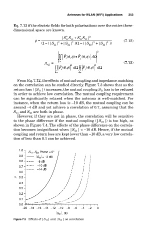
From Eq. 7.12, the effects of mutual coupling and impedance matching
on the correlation can be studied directly. Figure 7.3 shows that as the
return loss (|S |) increases, the mutual coupling S has to be reduced
11
21
in order to achieve low correlation. The mutual coupling requirement
can be significantly relaxed when the antenna is well-matched. For
instance, when the return loss is –10 dB, the mutual coupling can be
around –4 dB and yet achieve a correlation of 0.7, assuming that the
S and S are both in phase.
11
21
However, if they are not in phase, the correlation will be sensitive
to the phase difference if the mutual coupling (|S |) is too high, as
21
shown in Figure 7.4. The effects of the phase difference on the correla-
tion becomes insignificant when |S 21 | < –10 dB. Hence, if the mutual
coupling and return loss are kept lower than –10 dB, a very low correla-
tion of less than 0.1 can be achieved.
1.0
21
S 11 , S Phase = 0°
0.9 S = −3 dB
11
0.8 −6 dB
0.7 −10 dB
−14 dB
0.6
r 0.5
0.4
0.3
0.2
0.1
0.0
−20 −18 −16 −14 −12 −10 −8 −6 −4 −2 0
S , dB
21
Figure 7.3 Effects of |S 11 | and |S 21 | on correlation