
Page 50 - Antennas for Base Stations in Wireless Communications
P. 50
Fundamentals of Antennas 23
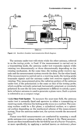
Figure 1.13 Anechoic chamber instrumentation block diagram
The antenna under test will rotate while the other antenna, referred
to as the testing probe, is fixed. If the measurement is carried out in
a transmitting mode, the antenna under test transmits signals while
rotating two dimensionally or three dimensionally depending on the
rotating mechanism. At the same time, the testing probe receives sig-
nals and the measurement system records the data. On the other hand,
if the measurement is carried out in a receiving mode, the testing probe
transmits signals and the antenna under test receives signals while
rotating. This measurement gives the radiation pattern of the antenna
under test, if the polarization is the same as that of the testing probe,
which could be vertically polarized, horizontally polarized, or circularly
polarized. In case the far-zone requirement is difficult to satisfy, a para-
bolic reflector antenna is used to generate a plane wave. Such a system
is referred to as a compact range.
1.3.2.2 Near-Field System To measure the near-zone field, the antenna
under test is normally fixed and operates in either a transmitting or
receiving mode, whereas the testing probe scans on a surface. The scan-
ning surface could be a flat plane, a cylindrical surface, or a spheri-
cal surface depending on the mechanical scheme of the measurement
system. Near the antenna under test, the system records the measured
data. 5,31
Planar near-field measurements are conducted by scanning a small
probe antenna over a planar surface, as in Figure 1.14a. These measure-
ments are then transformed to the far-field by use of a Fourier Transform,
or more specifically, by applying a method known as stationary phase