Page 53 - Antennas for Base Stations in Wireless Communications
P. 53

26      Chapter One

                             q   0   q
                          30            30

                    60                       60


                  90                           90
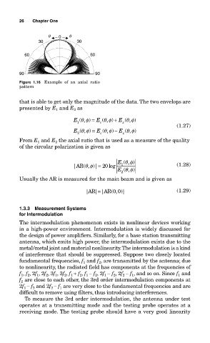
                  Figure  1.16  Example  of  an  axial  ratio
                  pattern

                  that is able to get only the magnitude of the data. The two envelops are
                  presented by E 1  and E 2  as
                                                             φ
                                            φ
                                       E ( , ) =  E ( , ) +  E ( , )
                                          θ
                                                           θ
                                                    φ
                                                  θ
                                                         x
                                        1
                                                 c
                                                                              (1.27)
                                                            ,φ
                                       E ( , ) =  E ( , ) −  E (θ, )
                                            φ
                                                  θ
                                                    φ
                                          θ
                                        2
                                                          x
                                                 c
                  From E  and E  the axial ratio that is used as a measure of the quality
                                2
                         1
                  of the circular polarization is given as
                                                          θ
                                       |AR ( , )|= 20 log  E 1 ( , ) φ        (1.28)
                                           θ
                                             φ
                                                          θ
                                                        E 2 ( , ) φ
                  Usually the AR is measured for the main beam and is given as
                                           |AR | |AR ( , )|                   (1.29)
                                                =
                                                      0
                                                        0
                  1.3.3  Measurement Systems
                  for Intermodulation
                  The intermodulation phenomenon exists in nonlinear devices working
                  in a high-power environment. Intermodulation is widely discussed for
                  the design of power amplifiers. Similarly, for a base station transmitting
                  antenna, which emits high power, the intermodulation exists due to the
                  metal/metal joint and material nonlinearity. The intermodulation is a kind
                  of interference that should be suppressed. Suppose two closely located
                                            and f , are transmitted by the antenna; due
                  fundamental frequencies, f 1  2
                  to nonlinearity, the radiated field has components at the frequencies of
                  f , f , 2f , 2f , 3f , 3f , f + f , f − f , 2f − f , 2f − f , and so on. Since f  and
                            2
                                                   1
                                                                              1
                                                             1
                         1
                                                      2
                   1
                      2
                                      1
                                            1
                                         2
                                               2
                                1
                                                         2
                                   2
                  f  are close to each other, the 3rd order intermodulation components at
                   2
                  2f − f  and 2f − f  are very close to the fundamental frequencies and are
                       2
                    1
                                  1
                              2
                  difficult to remove using filters, thus introducing interferences.
                    To measure the 3rd order intermodulation, the antenna under test
                  operates at a transmitting mode and the testing probe operates at a
                  receiving mode. The testing probe should have a very good linearity
   48   49   50   51   52   53   54   55   56   57   58