
Page 52 - Antennas for Base Stations in Wireless Communications
P. 52
Fundamentals of Antennas 25
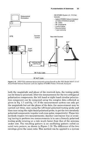
Figure 1.15 NSI VNA antenna measurement system based on the NSI Model 200 V- 5'×5'
Near-Field Vertical Scanner and the Agilent 8720ES Vector Network Analyzer
both the magnitude and phase of the received data, the testing probe
can be linearly polarized. After the measurement for the two orthogonal
polarization components, the left-hand or right-hand circular polariza-
tion component can be computed using the complex data collected as
given in Eq. 1.7 and Eq. 1.8. If the measurement system can only get
the magnitude but not the phase of the data, the measurement may be
carried out twice, once using the left-hand polarized testing probe and
then once using the right-hand polarized probe, to get the two circularly
polarized components (copular and cross-polar, respectively). These two
methods require two measurements. Another convenient way of avoid-
ing having to perform two measurements is to use a linearly polarized
testing probe rotating at a rate much faster than that of the antenna
under test. The resulting pattern is an oscillating pattern called an
axial ratio pattern, as shown in Figure 1.16. The difference of the two
envelops gives the axial ratio. This method can be applied to a system