
Page 51 - Antennas for Base Stations in Wireless Communications
P. 51
24 Chapter One
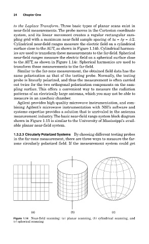
to the Laplace Transform. Three basic types of planar scans exist in
near-field measurements. The probe moves in the Cartesian coordinate
system, and its linear movement creates a regular rectangular sam-
pling grid with a maximum near-field sample spacing of ∆x = ∆y = l/2.
Cylindrical near-field ranges measure the electric field on a cylindrical
surface close to the AUT, as shown in Figure 1.14b. Cylindrical harmon-
ics are used to transform these measurements to the far-field. Spherical
near-field ranges measure the electric field on a spherical surface close
to the AUT, as shown in Figure 1.14c. Spherical harmonics are used to
transform these measurements to the far-field.
Similar to the far-zone measurement, the obtained field data has the
same polarization as that of the testing probe. Normally, the testing
probe is linearly polarized, and thus the measurement is often carried
out twice for the two orthogonal polarization components on the sam-
pling surface. This offers a convenient way to measure the radiation
patterns of an electrically large antenna, which you may not be able to
measure in an anechoic chamber.
Agilent provides high-quality microwave instrumentation, and com-
bining Agilent’s microwave instrumentation with NSI’s software and
systems expertise provides a solution that is unrivaled in the antenna
measurement industry. The basic near-field range system block diagram
shown in Figure 1.15 is similar to the University of Mississippi’s avail-
able planar near-field system.
1.3.2.3 Circularly Polarized Systems By choosing different testing probes
in the far-zone measurement, there are three ways to measure the far-
zone circularly polarized field. If the measurement system could get
(a) (b) (c)
Figure 1.14 Near-field scanning: (a) planar scanning, (b) cylindrical scanning, and
(c) spherical scanning