Page 105 - Applied Process Design For Chemical And Petrochemical Plants Volume III
P. 105

66131_Ludwig_CH10B  5/30/2001 4:18 PM  Page 73


                                                                    Heat Transfer                                           73

                                        T 1   210°F                             190
                          For tube side:  m   155,000 lb/hr                          T 1
                                       Cp   0.55 Btu/lb (°F)                    180
                                        t 1   135°F; t 2   168°F
                                                                                170
                       Now, estimate the exchanger performance if the hot fluid  160
                     (shell-side) is to be increased 35% greater than the original  150
                                     2
                     design: A   187 ft . Note that the method does not specifi-
                     cally incorporate fouling, but it should be acknowledged.  140
                       Determine the outlet temperature when U is established.  TEMPERATURE °F  130

                       1. On shell side: M   1.35 (65,000)   87,750 lb/hr; the Cp s and  120   DEWPOINT 120°F.
                            T 1 are kept the same.                                   t
                       2. On tube side: m, Cp, t 1 , U, and A remain the same.  110  2
                                                                                                                    T (105°F)
                                                                                                                     2
                                         T 1   T 2
                       3. Now calculate  R       m Cp >MCPs                     100
                                                                                            105°F
                                         t 2   t 1
                                                                                 90       (110 – 5)                 t (90°F)
                                                                                                                     1
                            1155,0002 10.552 > 187,7502 10.582
                                                                                 80
                            1.675                                                   0       0.5       1.0      1.5       2.0
                       4. UA/(mc)   (170)(187) / (155,000)(0.55)   0.37, see Figure         HEAT LOAD, BTU/HR. (MM)
                         10-35.
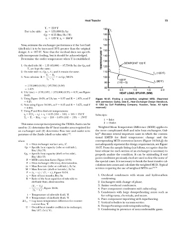
                       5. Using Figure 10-35, at UA/mc   0.37 and R   1.675, read P  Figure 10-37.  Finding a counterflow weighted MTD. (Reprinted
                           0.25.                                           with permission: Gulley, Dale E., Heat Exchanger Design Handbook,
                       6. Now using Figure 10-34A, at P   0.25 and R   1.675, read F  © 1968 by Gulf Publishing Company, Houston, Texas. All rights
                           0.954.                                          reserved.)
                       7. Using P and R to find exit temperatures:
                         t 2   P(T 1   t 1 )   t 1   0.25 (210   133)   133   152°F  Subscripts:
                         T 2   T 1   R(t 2   t 1 )   210  1.675 (152   133)   178°F
                                                                                 1   Inlet
                                                                                 2   Outlet
                       This same concept incorporating the TEMA charts can be
                                             2
                     used to (1) determine the ft heat transfer area required for  Weighted Mean Temperature Difference (MTD) applies to
                     an exchanger and (2) determine flow rate and outlet tem-  the more complicated shell and tube heat exchangers. Gul-
                                                                             59
                                                        135
                     perature of the fluids (shell or tube side) .         ley discusses several important cases in which the conven-
                                                                           tional LMTD for fluid temperature change and the
                     where                                                 corresponding MTD correction factors (Figure 10-34A—J) do
                                                       2
                           A   Heat exchanger surface area, ft .           not adequately represent the design requirements, see Figure
                          Cp   Specific heat capacity (tube or cold side),  10-37. From the sample listing that follows, recognize that the
                               Btu/(lb)(°F)                                heat release for each section of an exchanger is necessary to
                         Cp s   Specific heat capacity (shell or hot side),  properly analyze the condition. It can be misleading if end
                               Btu/(lb)(°F)                                point conditions previously cited are used to describe some of
                           F   MTD correction factor, Figure 10-34.        the special cases. It is necessary to break the heat transfer cal-
                           F   Heat exchanger efficiency, dimensionless.
                          m   Mass flow rate (tube or cold side), lb/hr.   culations into zones and calculate the weighted MTD. Typical
                                                                                                                   59, 70
                          M   Mass flow rate (shell or hot side), lb/hr.   services requiring the use of weighted MTS’s are
                           P   (t 2   t 1 ) / (T 1   t 1 ), Figure 10-34.
                           q   Rate of heat transfer, Btu/hr.                1. Overhead condensers with steam and hydrocarbon
                           R   Ratio of the heat capacities of tube-side to    condensing.
                               shell-side fluid, dimensionless               2. Exchangers with change of phase.
                                                                             3. Amine overhead condensers.
                               1T 1   T 2 2
                                      , Figure 10-34.                        4. Pure component condensers with subcooling.
                               1t 2   t 1 2
                                                                             5. Condensers with large desuperheating zones such as
                           t   Temperature of tube-side fluid, °F.
                                                                               for refrigerants, chemicals, and steam.
                           T   Temperature of shell-side fluid, °F.
                                                                             6. Pure component vaporizing with superheating.
                         T 1m   Log mean temperature difference for counter-
                                                                             7. Vertical reboilers in vacuum service.
                               current flow, °F.
                                                                             8. Desuperheating-condensing-subcooling.
                           U   Overall heat transfer coefficient in exchanger,
                                                                             9. Condensing in presence of noncondensable gases.
                                    2
                               Btu/(ft ) (hr)(°F).
   100   101   102   103   104   105   106   107   108   109   110