
Page 127 - Applied Process Design For Chemical And Petrochemical Plants Volume III
P. 127
66131_Ludwig_CH10D 5/30/2001 4:29 PM Page 93
Heat Transfer 93
Overall Estimated Fouling
In Outside Type Velocities, Ft/Sec Coeffi- Temp. Over-
Tubes Tubes Equipment Tube Shell cient Range, °F Tube Shell all
Chilled water Air-chlorine (part. cond.) U . . . . . . 08—15 00008—15 (C)
0.0015 0.005 . . .
20—30 000010—15 (Co)
Water Light HC, cool and cond. H . . . . . . 35—90 270—900 0.0015 0.003 . . .
{
Water Ammonia H . . . . . . 140—165 120—900 0.001 0.001 . . .
Water Ammonia U . . . . . . 280—300 110—900 0.001 0.001 . . .
Air-Water vapor Freon KU . . . . . . 10—50
60—10 . . . . . . 0.01
10—20
{ }
C. Reboiling
Steam H 7—8 ... 130—150 180—160 . . . . . . 0.005
Solvent, Copper-NH 3
C 4 Unsat. Steam H . . . . . . 095—115 095—150 . . . . . . 0.0065
Chloro. HC Steam VT . . . . . . 35—25 300—350 0.001 0.001 . . .
Chloro. unsat. HC Steam VT . . . . . . 100—140 230—130 0.001 0.001 . . .
Chloro. ethane Steam VT . . . . . . 090—135 300—350 0.001 0.001 . . .
Chloro. ethane Steam U . . . . . . 50—70 030—190 0.002 0.001 . . .
Solvent (heavy) Steam H . . . . . . 070—115 375—300 0.004 0.0005 . . .
Mono—di-ethanolamines Steam VT . . . . . . 210—155 450—350 0.002 0.001 . . .
Organics, acid, water Steam VT . . . . . . 060—100 450—300 0.003 0.0005 . . .
Amines and water Steam VT . . . . . . 120—140 360—250 0.002 0.0015 . . .
Steam Naphtha frac. Annulus, long. F.N. . . . . . . 15—20 270—220 0.0035 0.0005 . . .
Propylene C 2 , C 2 KU ... ... 120—140 150—400 0.001 0.001 . . .
Propylene-butadiene Butadiene, unsat. H . . . 25—35 15—18 400—100 . . . . . . 0.02
*Unless specified, all water is untreated, brackish, bay or sea.
Notes: H horizontal, fixed or floating tubesheet T thermosiphon V vertical (C) cooling range t
U U-tube horizontal bundle v variable R reboiler (Co) condensing range
K kettle type HC hydrocarbon Data/results based on actual and specific industrial equipment.
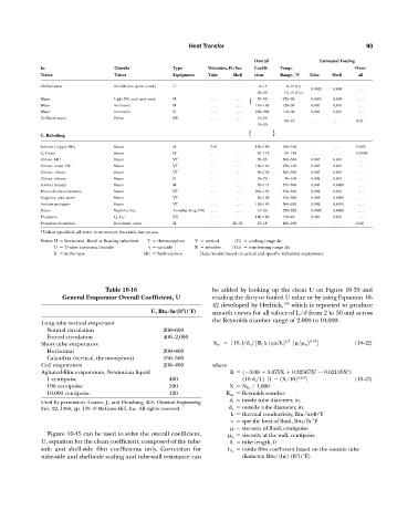
Table 10-16 be added by looking up the clean U on Figure 10-39 and
General Evaporator Overall Coefficient, U reading the dirty or fouled U value or by using Equation 10-
42 developed by Hedrick, 159 which is reported to produce
2
U, Btu/hr(ft )(°F) smooth curves for all values of L/d from 2 to 50 and across
the Reynolds number range of 2,000 to 10,000.
Long-tube vertical evaporator
Natural circulation 200—600
Forced circulation 400—2,000
Short-tube evaporators h io 116.1>d o 2 3B I k 1c >k2 1>3 1 > w 2 0.14 4 (10-42)
Horizontal 200—400
Calandria (vertical, thermosiphon) 150—500
Coil evaporators 200—400 where
2
3
Agitated-film evaporators, Newtonian liquid B ( 3.08 3.075X 0.32567X 0.02185X )
1 centipoise 400 (10 d i /L) [1 (X/10) 0.256 ] (10-43)
100 centipoise 300 X N Re / 1,000
10,000 centipoise 120 R Re Reynolds number
Used by permission: Coates, J., and Pressburg, B.S. Chemical Engineering, d i inside tube diameter, in.
Feb. 22, 1960, pp. 139. © McGraw-Hill, Inc. All rights reserved. d o outside tube diameter, in.
k thermal conductivity, Btu/hr-ft-°F
c specific heat of fluid, Btu/lb-°F
viscosity of fluid, centipoise
Figure 10-45 can be used to solve the overall coefficient, w viscosity at the wall, centipoise
U, equation for the clean coefficient, composed of the tube- L tube length, ft
side and shell-side film coefficients only. Correction for h io inside film coefficient based on the outside tube
2
tube-side and shell-side scaling and tube-wall resistance can diameter, Btu/(hr) (ft )(°F)