Page 123 - Applied Process Design For Chemical And Petrochemical Plants Volume III
P. 123

66131_Ludwig_CH10C  5/30/2001 4:21 PM  Page 90


                       90                        Applied Process Design for Chemical and Petrochemical Plants

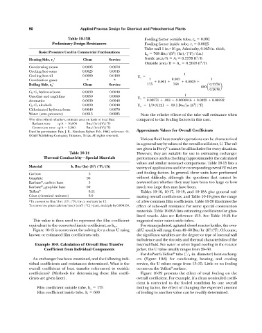
                                           Table 10-13B                          Fouling factor outside tube, r o   0.001
                                   Preliminary Design Resistances                Fouling factor inside tube, r i   0.0025
                                                                                 Tube wall 1 in.—16 ga, Admiralty, 0.065-in. thick,
                            Basis: Pressures Used in Commercial Fractionations                 2
                                                                                 k w   768 Btu/(ft ) (hr)/(°F)/(in.)
                                                                                 Inside area/ft   A i   0.2278 ft /ft
                                                                                                           2
                       Heating Side, r p '        Clean        Service
                                                                                                             2
                                                                                 Outside area/ft   A o   0.2618 ft /ft
                       Condensing steam           0.0005       0.0010
                       Cooling hot water          0.0025       0.0045
                                                                                                     1
                       Cooling hot oil            0.0080       0.0100        U o
                       Combustion gases             *             *                1    0.001    0.065    0.0025    1
                       Boiling Side, r h '        Clean        Service            175          768                0.2278
                                                                                                             600a      b
                                                                                                                  0.2618
                       C 2 —C 4 hydrocarbons      0.0030       0.0040
                       Gasoline and naphthas      0.0050       0.0060        U o                     1
                       Aromatics                  0.0030       0.0040             0.00571   .001   0.0000846   0.0025   0.00192
                                                                                                          2
                       C 2 —C 7 alcohols          0.0030       0.0040        U o      1>0.01121     89.1 Btu>hr 1ft 2 1°F2
                       Chlorinated hydrocarbons   0.0040       0.0070
                       Water (atm. pressure)      0.0015       0.0025          Note the relative effects of the tube wall resistance when
                       *For direct-fired reboilers, estimate area on basis of heat flux:  compared to the fouling factors in this case.
                         Radiant zone  q/A   10,000  Btu/(hr)(ft )(°F)
                                                            2
                                                            2
                         Convection zone q/A   3,500  Btu/(hr)(ft )(°F)
                       Used by permission: Fair, J. R., Petroleum Refiner. Feb. 1960, reference 45.  Approximate Values for Overall Coefficients
                       ©Gulf Publishing Company, Houston, Texas. All rights reserved.
                                                                               Various fluid heat transfer operations can be characterized
                                                                             in a general way by values of the overall coefficient, U. The val-
                                                                             ues given in Perry cannot be all-inclusive for every situation.
                                                                                            94
                                           Table 10-14                       However, they are suitable for use in estimating exchanger
                              Thermal Conductivity—Special Materials         performance and in checking (approximately) the calculated
                                                                             values and similar nonexact comparisons. Table 10-15 lists a
                       Material             k, Btu/(hr) (ft ) (°F)/(ft)
                                                       2
                                                                             variety of applications and the corresponding overall U values
                                                                             and fouling factors. In general, these units have performed
                       Carbon                        3
                       Graphite                     90                       without difficulty, although the questions that cannot be
                             ®
                       Karbate , carbon base         3                       answered are whether they may have been too large or how
                             ®
                       Karbate , graphite base      80                       much too large they may have been.
                       Teflon ®                      0.11                      Tables 10-16, 10-17, 10-18, and 10-18A give general esti-
                       Glass (chemical resistant)    6.9                     mating overall coefficients, and Table 10-19 gives the range
                       *To convert to Btu/(hr) (ft ) (°F)/(in.), multiply by 12.  of a few common film coefficients. Table 10-20 illustrates the
                                          2
                       To convert to gram calories/(sec) (cm ) (°C)/(cm), multiply by 0.004134.  effect of tube-wall resistance for some special construction
                                                 2
                                                                             materials. Table 10-20A lists estimating coefficients for glass-
                                                                             lined vessels. Also see Reference 215. See Table 10-24 for
                         This value is then used to represent the film coefficient  suggested water rates inside tubes.
                       equivalent to the converted inside coefficient, as h io .  For steam jacketed, agitated closed reactor kettles, the over-
                                                                                                                 2
                         Figure 10-45 is convenient for solving for a clean U using  all U usually will range from 40—60 Btu/hr (ft )(ºF). Of course,
                       known or estimated film coefficients only.            the significant variables are the degree or type of internal wall
                                                                             turbulence and the viscosity and thermal characteristics of the
                          Example 10-8. Calculation of Overall Heat Transfer  internal fluid. For water or other liquid cooling in the reactor
                               Coefficient from Individual Components        jacket, the U value usually ranges from 20—30.
                                                                                               ®
                                                                               For duPont’s Teflon tube ( / 4 -in. diameter) heat exchang-
                                                                                                      1
                         An exchanger has been examined, and the following indi-  ers (Figure 10-8) for condensing, heating, and cooling
                       vidual coefficients and resistances determined. What is the  service, the U values range from 15—35. Little or no fouling
                       overall coefficient of heat transfer referenced to outside  occurs on the Teflon surface.
                                                                                              ®
                       coefficients? (Methods for determining these film coeffi-  Figure 10-39 presents the effect of total fouling on the
                       cients are given later).                              overall coefficient. For example, if a clean nonfouled coeffi-
                                                                             cient is corrected to the fouled condition by one overall
                           Film coefficient outside tube, h o   175          fouling factor, the effect of changing the expected amount
                           Film coefficient inside tube, h i   600           of fouling to another value can be readily determined.
   118   119   120   121   122   123   124   125   126   127   128