
Page 119 - Applied Process Design For Chemical And Petrochemical Plants Volume III
P. 119
66131_Ludwig_CH10C 5/30/2001 4:21 PM Page 86
86 Applied Process Design for Chemical and Petrochemical Plants
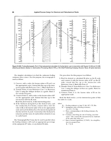
Figure 10-43C. Fouling Nomograph, Part 3. Final and practical calculation for fouling factor; use in conjunction with Figures 10-43A and 10-43B.
(Used by permission: Zanker, A., Hydrocarbon Processing. March 1978, p. 148. ©Gulf Publishing Company, Houston, Texas. All rights reserved.)
The simplest calculation is to find the unknown fouling The procedure for this purpose is as follows:
resistance after a time t. For this purpose, the nomograph is
1) Find the desired or calculated R value on the R t scale
used as follows:
and connect it with the known value of R* on the R*
scale; extend this line up to the intersection with
1) Connect, with a ruler, the known values of B and t on 1
Reference Line 2. Mark this Point A .
the appropriate scales. Extend this line up to the inter- 1
2) Transfer Point A from Reference Line 2 to Reference
section point with Reference Line 1. Mark this Point A.
Line 1 using the oblique tie-lines as a guide. Mark the
2) Transfer Point A from Reference Line 1 to Reference transferred Point A.
Line 2, using the oblique tie-lines as a guide. Mark A 1
3) Connect Point A to the known value of B on the
the transferred point.
1
3) Connect Point A , with a ruler, to the known value of R* appropriate scale.
on the appropriate scale. Extend this line up to the Read the final result, t, at the intersection point of this
intersection with the R t scale. line with the t scale.
Read the final result, R t , at this intersecting point.
4) If the thickness of deposit X t is the desired value, and where
2
the conductivity, K is known, connect with a ruler the R t Fouling resistance at time T, (hr) (ft ) (°F)/Btu
value of R t to the known value of K on the appropriate R* Asymptotic value of fouling resistance,
2
scale and read the thickness X t at the intersection point of (hr) (ft ) (°F)/Btu
t Time, corresponding to the fouling resistance, R t ,
this line with the X t scale. Conversely, if the thickness X t
(any units)
is known and the value of conductivity is desired, it can
B Constant, describing the rate of fouling, (any time
be easily found. –1
units) (the constant B, is measured in the reciprocals
of the same time units, as t)
The Nomograph Part 3 may also be used to predict when e Base of natural logarithms, (2.71821). As a simplifica-
the fouling resistance will reach an appropriate percentage tion it is assumed that:
of the asymptotic R* value, or any desired R value. R t X t /K