
Page 120 - Applied Process Design For Chemical And Petrochemical Plants Volume III
P. 120
66131_Ludwig_CH10C 5/30/2001 4:21 PM Page 87
Heat Transfer 87
X t Thickness or deposit formed at time t (ft) approach that time when cleaning of the exchanger is
K Thermal conductivity of deposited material, required. Gas flows are used because usually the gas film
(Btu/(hr) (ft) (°F).” controls in a gas-liquid exchanger.
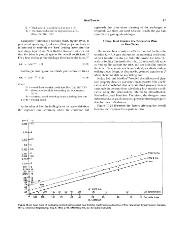
Ganapathy 144 presents a working chart, Figure 10-44, to Overall Heat Transfer Coefficients for Plain
plot actual operating U a values to allow projection back to or Bare Tubes
infinity and to establish the “base” fouling factor after the
operating elapsed time. Note that the flow rate inside or out- The overall heat transfer coefficient as used in the rela-
side the tubes is plotted against the overall coefficient, U. tionship Q UA t is the sum of the individual coefficient
For a heat exchanger in which gas flows inside the tubes. 144 of heat transfer for the (a) fluid film inside the tube, (b)
scale or fouling film inside the tube, (c) tube wall, (d) scale
1>U A W 0.8 B (10-35) or fouling film outside the tube, and (e) fluid film outside
the tube. These must each be individually established when
and for gas flowing over or outside plain or finned tubes: making a new design, or they may be grouped together as U
when obtaining data on an existing unit.
1>U A W 0.6 B (10-36) Najjar, Bell, and Maddox 162 studied the influence of phys-
ical property data on calculated heat transfer film coeffi-
where cients and concluded that accurate fluid property data is
2
U overall heat transfer coefficient, Btu/(hr) (ft ) (°F)
extremely important when calculating heat transfer coeffi-
W flow rate of the fluid controlling the heat transfer,
cients using the relationships offered by Dittus-Boelter,
lb/hr
Sieder-Tate, and Petukhov. Therefore, the designer must
B constant, equal to fouling factor at infinity flow rate
strive to arrive at good consistent physical/thermal property
F or ff fouling factor
data for these calculations.
As the value of B or the fouling factor increases with time, Figure 10-28 illustrates the factors affecting the overall
the engineer can determine when the condition will heat transfer expressed in equation form:
Figure 10-44. Keep track of fouling by monitoring the overall heat transfer coefficient as a function of flow rate. (Used by permission: Ganapa-
thy, V., Chemical Engineering, Aug. 6, 1984, p. 94. ©McGraw-Hill, Inc. All rights reserved.)