
Page 115 - Applied Process Design For Chemical And Petrochemical Plants Volume III
P. 115
66131_Ludwig_CH10C 5/30/2001 4:21 PM Page 82
82 Applied Process Design for Chemical and Petrochemical Plants
Table 10-13
Suggested Fouling Factors in Petrochemical Processes
2
r (hr) (ft ) (°F)/Btu
Temperature Range
Fluid Velocity, Ft/Sec 100°F 100°F
Waters:
Sea (limited to 125°F max.) 4 0.002 0.003
7 0.0015 0.002
River (settled) 2 0.002 0.002—0.003
4 0.0005—0.0015 0.001—0.0025
River (treated and settled) 2 0.0015 0.002
4 0.001 0.0015
4 mils baked phenolic coating 65 0.0005 Fouling Factor, hr-ft 2 -°F/Btu Fouling Factor
15 mils vinyl-aluminum coating 0.001
Condensate (100°—300°F) 2 0.001 0.002—0.0004
4 0.0005 0.001
Steam (saturated) oil free 0.0005—0.0015
with traces oil 0.001—0.002
ethylene, propylene, butane-clean) }
Light hydrocarbon liquids
(methane, ethane, propane,
Light hydrocarbon vapors: (clean) 0.001
Chlorinated hydrocarbons
(carbon tetrachloride,
chloroform, ethylene dichloride,
etc.)
Liquid 0.001 0.002
Condensing 0.001 0.0015
Boiling 0.002 0.002
Refrigerants (vapor condensing
and liquid cooling)
Ammonia 0.001
Propylene 0.001
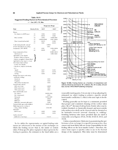
Chloro-fluoro-refrigerants 0.001 Figure 10-40A. Fouling factors as a function of temperature and
Caustic liquid, salt-free velocity. (Used by permission: W. L. Nelson, No. 94 in series, Oil and
20% (steel tube) 3—8 0.0005 Gas Journal. ©PennWell Publishing Company.)
50% (nickel tube) 6—9 0.001
73% (nickel tube) 6—9 0.001
Gases (industrially clean)
Air (atmos.) 0.0005—0.001 reasonable starting point. It is not wise to keep adjusting the
Air (compressed) 0.001 estimated (or other) fouling to achieve a specific overall
Flue gases 0.001—0.003 heat transfer coefficient, U, which is the next topic to be dis-
Nitrogen 0.0005
cussed.
Hydrogen 0.0005
Fouling generally can be kept to a minimum provided
Hydrogen (saturated with water) 0.002
Polymerizable vapors with inhibitor 0.003—0.03 that proper and consistent cleaning of the surface takes
High temperature cracking or place. Kern 269 discusses fouling limits. Inside tubes may be
coking, polymer buildup 0.02—0.06 rodded, brushed, or chemically cleaned, and most outside
Salt brines
tube surfaces in a shell can be cleaned only by chemical or
(125°F max.) 2 0.003 0.004
by hydraulic/corncob external cleaning or rodding/
4 0.002 0.003
Carbon dioxide 93 brushing between tube lanes provided that the shell is
(sublimed at low temp.) 0.2—0.3 removable as in Figures 10-1A, 10-1B, 10-1D—F, 10-1I, and
10-1K.
Unless a manufacturer/fabricator is guaranteeing the per-
In the tables the representative or typical fouling resis- formance of an exchanger in a specific process service, they
tances are referenced to the surface of the exchanger on cannot and most likely will not accept responsibility for the
which the fouling occurs—that is, the inside or outside fouling effects on the heat transfer surface. Therefore, the
tubes. Unless specific plant/equipment data represents the owner must expect to specify a value to use in the thermal
fouling in question, the estimates in the listed tables are a design of the equipment. This value must be determined