
Page 112 - Applied Process Design For Chemical And Petrochemical Plants Volume III
P. 112
66131_Ludwig_CH10C 5/30/2001 4:21 PM Page 79
Heat Transfer 79
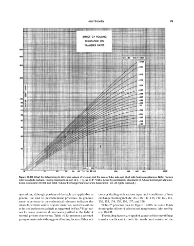
Figure 10-39. Chart for determining U-dirty from values of U-clean and the sum of tube-side and shell-side fouling resistances. Note: Factors
2
refer to outside surface. Fouling resistance is sum of (r i r o ), as hr-ft -ºF/Btu. (Used by permission: Standards of Tubular Exchanger Manufac-
turers Association ©1959 and 1968. Tubular Exchanger Manufacturers Association, Inc. All rights reserved.)
operations, although portions of the table are applicable to erences dealing with various types and conditions of heat
general use and to petrochemical processes. In general, exchanger fouling include 145, 146, 147, 148, 149, 150, 151,
some experience in petrochemical mixtures indicates the 152, 153, 154, 155, 156, 157, and 158.
89
values for certain waters, organic materials, and a few others Nelson presents data in Figure 10-40A on some fluids
44
to be too low but not as high as suggested by Fair. High val- showing the effects of velocity and temperature. Also see Fig-
ues for some materials do not seem justified in the light of ure 10-40B.
normal process economics. Table 10-13 presents a selected The fouling factors are applied as part of the overall heat
group of materials with suggested fouling factors. Other ref- transfer coefficient to both the inside and outside of the