
Page 114 - Applied Process Design For Chemical And Petrochemical Plants Volume III
P. 114
66131_Ludwig_CH10C 5/30/2001 4:21 PM Page 81
Heat Transfer 81
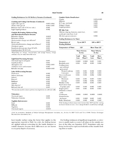
Fouling Resistances for Oil Refinery Streams (Continued) Catalytic Hydro Desulfurizer:
Charge 0.004—0.005
Cracking and Coking Unit Streams (Continued) Effluent 0.002
Light coker gas oil 0.003—0.004 H.T. sep. overhead 0.002
Heavy coker gas oil 0.004—0.005 Stripper charge 0.003
Bottoms slurry oil (4.5 ft/sec min.) 0.003 Liquid products 0.002
Light liquid products 0.002 HF Alky Unit:
Catalytic Reforming, Hydrocracking, Alkylate, deprop. bottoms, main fract. 0.003
and Hydrodesulfurization Streams: overhead, main fract. feed
Reformer charge 0.0015 All other process streams 0.002
Reformer effluent 0.0015 Fouling Resistances for Water
Hydrocracker charge and effluent* 0.002
Recycle gas 0.001 Temperature of Up to 240°F 240 to 400°F
Hydrodesulfurization charge and effluent* 0.002 Heating Medium
Overhead vapors 0.001
Temperature of Water 125° More Than 125°
Liquid product greater than 50°A.P.I. 0.001
Liquid product 30—50°A.P.I. 0.002
Water Velocity Water Velocity
*Depending on charge, characteristics and storage history, charge Ft/Sec Ft/Sec
resistance may be many times this value.
3 and More 3 and More
Less Than 3 Less Than 3
Light Ends Processing Streams:
Overhead vapors and gases 0.001 Sea water 0.0005 0.0005 0.001 0.001
Liquid products 0.001 Brackish water 0.002 0.001 0.003 0.002
Absorption oils 0.002—0.003 Cooling tower
Alkylation trace acid streams 0.002 and artificial
Reboiler streams 0.002—0.003 spray pond:
Lube Oil Processing Streams: Treated makeup 0.001 0.001 0.002 0.002
Feed stock 0.002 Untreated 0.003 0.003 0.005 0.004
Solvent feed mix 0.002 City or well water 0.001 0.001 0.002 0.002
Solvent 0.001 River water:
Extract* 0.003 Minimum 0.002 0.001 0.003 0.002
Raffinate 0.001 Average 0.003 0.002 0.004 0.003
Asphalt 0.005 Muddy or silty 0.003 0.002 0.004 0.003
Wax slurries* 0.003 Hard (more than
Refined lube oil 0.001 15 grains/gal) 0.003 0.003 0.005 0.005
Engine jacket 0.001 0.001 0.001 0.001
*Precautions must be taken to prevent wax deposition on cold tube walls.
Distilled or closed
cycle
Visbreaker: Condensate 0.0005 0.0005 0.0005 0.0005
Overhead vapor 0.003 Treated boiler
Visbreaker bottoms 0.010 feedwater 0.001 0.0005 0.001 0.001
Boiler blowdown 0.002 0.002 0.002 0.002
Naphtha Hydrotreater:
Feed 0.003 If the heating medium temperature is more than 400°F and the cooling
Effluent 0.002 medium is known to scale, these ratings should be modified accordingly.
Naphtha 0.002
Overhead vapors 0.0015
(Used by permission: Standards of Tubular Exchanger Manufacturers Association, Inc., Section 10, RGP T-2.32 and T-2.4, ©1988. Tubular Exchanger
Manufacturers Association, Inc.)
heat transfer surface using the factor that applies to the For fouling resistances of significant magnitude, a correc-
appropriate material or fluid. As a rule, the fouling factors tion is usually made to convert all values to the outside sur-
are applied without correcting for the inside diameter to face of the tube; see Equation 10-37. Sometimes only one
outside diameter, because these differences are not known factor is selected to represent both sides of the transfer foul-
to any great degree of accuracy. ing films or scales.