
Page 130 - Applied Process Design For Chemical And Petrochemical Plants Volume III
P. 130
66131_Ludwig_CH10D 5/30/2001 4:29 PM Page 96
96 Applied Process Design for Chemical and Petrochemical Plants
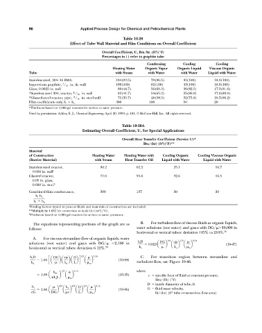
Table 10-20
Effect of Tube Wall Material and Film Conditions on Overall Coefficient
2
Overall Coefficient, U, Btu/hr. (ft )(°F)
Percentages in ( ) refer to graphite tube
Condensing Cooling Cooling
Heating Water Organic Vapor Organic Liquid Viscous Organic
Tube with Steam with Water with Water Liquid with Water
Stainless steel, 304—16 BWG 184(92.5) 079(96.5) 43(100) 18.9(100)
3
Impervious graphite, / 16 in. tk. wall 199(100) 082(100) 43(100) 18.9(100)
Glass, 0.0625 in. wall 089(44.7) 056(68.3) 36(82.5) 17.3(91.6)
21
*Stainless steel 304, reactor, / 32 in. wall 083(41.7) 054(65.2) 35(80.9) 17.0(89.9)
*Glassed-steel reactor, pipe, / 16 in. steel wall 071(35.7) 048(58.5) 32(73.8) 16.3(86.2)
11
300 100 50 20
Film coefficients only, h i h o
*Thickness based on 1,000-gal reactors for service at same pressure.
Used by permission: Ackley, E. J., Chemical Engineering, April 20, 1959, p. 181. © McGraw-Hill, Inc. All rights reserved.
Table 10-20A
Estimating Overall Coefficient, U, for Special Applications
Overall Heat Transfer Coefficient (Service U)*
2
Btu/(hr) (ft )(°F)**
Material
of Construction Heating Water Heating Water with Cooling Organic Cooling Viscous Organic
(Barrier Material) with Steam Heat Transfer Oil Liquid with Water Liquid with Water
Stainless steel reactor, 90.2 62.2 35.1 16.7
0.656 in. wall
Glasteel reactor, 77.0 55.6 32.6 16.5
0.05 in. glass,
0.688 in. steel
Combined film conductance, 300 137 50 20
h i h o
h i h o
*Fouling factors typical to process fluids and materials of construction are included.
2
**Multiply by 4.882 for conversion to kcal/(hr)(m )(°C).
Thickness based on 1,000-gal reactors for service at same pressures.
The equations representing portions of the graph are as B. For turbulent flow of viscous fluids as organic liquids,
follows: water solutions (not water) and gases with DG/ 10,000 in
horizontal or vertical tubes: deviation 115% to 210%. 70
A. For viscous streamline flow of organic liquids, water
h i D DG 0.8 c 1>3 0.14
solutions (not water) and gases with DG/ 2,100 in 0.023a b a b a b (10-47)
horizontal or vertical tubes: deviation 6 12%. 70 k a k a w
h i D DG c D 1>3 0.14 C. For transition region between streamline and
1.86 ca ba ba bd a b (10-44)
k a k a L w turbulent flow, use Figure 10-46.
1>3 0.14 where
4 wc
1.86 a b a b (10-45) c specific heat of fluid at constant pressure,
k a L w
Btu/(lb) (°F)
D inside diameter of tube, ft
2>3 2>3 1>3 0.14
h i k a D
1.86 a b a b a b a b (10-46) G fluid mass velocity,
cG DG c L w lb/(hr) (ft tube cross-section flow area)
2