
Page 133 - Applied Process Design For Chemical And Petrochemical Plants Volume III
P. 133
66131_Ludwig_CH10D 5/30/2001 4:30 PM Page 98
98 Applied Process Design for Chemical and Petrochemical Plants
h i film heat transfer coefficient inside tube, A. For turbulent flow:
2
Btu/(hr) (ft )(°F)
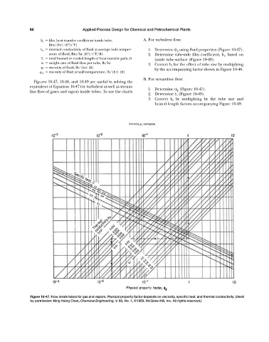
k a thermal conductivity of fluid at average bulk temper- 1. Determine p using fluid properties (Figure 10-47).
2
ature of fluid, Btu/hr (ft )/(°F/ft) 2. Determine tube-side film coefficient, h i , based on
L total heated or cooled length of heat transfer path, ft inside tube surface (Figure 10-48).
w weight rate of fluid flow per tube, lb/hr
3. Correct h i for the effect of tube size by multiplying
viscosity of fluid, lb/(hr) (ft)
by the accompanying factor shown in Figure 10-48.
w viscosity of fluid at wall temperature, lb/(hr) (ft)
B. For streamline flow:
Figures 10-47, 10-48, and 10-49 are useful in solving the
equivalent of Equation 10-47 for turbulent as well as stream-
1. Determine p (Figure 10-47).
line flow of gases and vapors inside tubes. To use the charts
2. Determine h i (Figure 10-49).
3. Correct h i by multiplying by the tube size and
heated length factors accompanying Figure 10-49.
Figure 10-47. Flow inside tubes for gas and vapors. Physical property factor depends on viscosity, specific heat, and thermal conductivity. (Used
by permission: Ning Hsing Chen, Chemical Engineering, V. 66, No. 1, ©1959. McGraw-Hill, Inc. All rights reserved.)