
Page 135 - Applied Process Design For Chemical And Petrochemical Plants Volume III
P. 135
66131_Ludwig_CH10D 5/30/2001 4:30 PM Page 100
100 Applied Process Design for Chemical and Petrochemical Plants
2
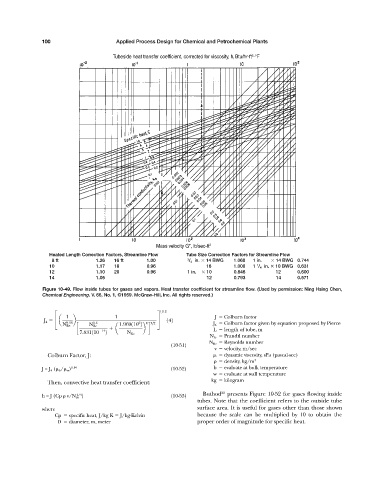
Tubeside heat transfer coefficient, corrected for viscosity, h i Btu/hr-ft -°F
Mass velocity G , lb/sec-ft 2
Heated Length Correction Factors, Streamline Flow Tube Size Correction Factors for Streamline Flow
08 ft 1.26 16 ft 1.00 3 / 4 in. 14 BWG 1.060 1 in. 14 BWG 0.744
1
10 1.17 18 0.96 16 1.000 1 / 4 in. 10 BWG 0.631
12 1.10 20 0.96 1 in. 10 0.846 12 0.600
14 1.05 12 0.793 14 0.571
Figure 10-49. Flow inside tubes for gases and vapors. Heat transfer coefficient for streamline flow. (Used by permission: Ning Hsing Chen,
Chemical Engineering, V. 66, No. 1, ©1959. McGraw-Hill, Inc. All rights reserved.)
1>12
1 1 J Colburn factor
J 4 £a b § 142
9.36 1.6 6 8 3>2 J 4 Colburn factor given by equation proposed by Pierce
N Re N Re 1.969110 2
c a b d L length of tube, m
7.831110 14 2 N Re
N Pr Prandtl number
N Re Reynolds number
(10-51)
v velocity, m/sec
Colburn Factor, J: dynamic viscosity, sPa (pascal-sec)
density, kg/m 3
J = J 4 ( b / w ) 0.14 (10-52) b evaluate at bulk temperature
w evaluate at wall temperature
Then, convective heat transfer coefficient: kg kilogram
22
2/3
h = J (Cp v/N Pr ) (10-53) Buthod presents Figure 10-52 for gases flowing inside
tubes. Note that the coefficient refers to the outside tube
where surface area. It is useful for gases other than those shown
Cp specific heat, J/kg K J/kg-Kelvin because the scale can be multiplied by 10 to obtain the
D diameter, m, meter proper order of magnitude for specific heat.