Page 139 - Applied Process Design For Chemical And Petrochemical Plants Volume III
P. 139

66131_Ludwig_CH10D  5/30/2001 4:30 PM  Page 104


                       104                       Applied Process Design for Chemical and Petrochemical Plants


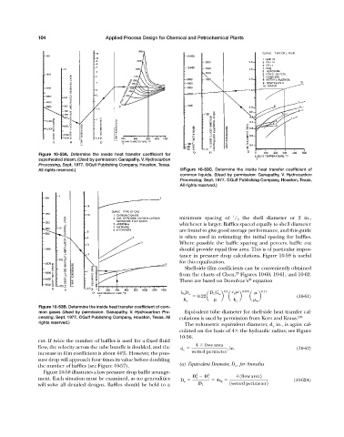
                       Figure 10-53A.  Determine the inside heat transfer coefficient for
                       superheated steam. (Used by permission: Ganapathy, V. Hydrocarbon
                       Processing, Sept. 1977. ©Gulf Publishing Company, Houston, Texas.
                       All rights reserved.)                                 ©Figure 10-53C.  Determine the inside heat transfer coefficient of
                                                                             common liquids. (Used by permission: Ganapathy, V. Hydrocarbon
                                                                             Processing, Sept. 1977. ©Gulf Publishing Company, Houston, Texas.
                                                                             All rights reserved.)


                                                                                                 1
                                                                             minimum spacing of  / 5 the shell diameter or 2 in.,
                                                                             whichever is larger. Baffles spaced equally to shell diameter
                                                                             are found to give good average performance, and this guide
                                                                             is often used in estimating the initial spacing for baffles.
                                                                             Where possible the baffle spacing and percent baffle cut
                                                                             should provide equal flow area. This is of particular impor-
                                                                             tance in pressure drop calculations. Figure 10-59 is useful
                                                                             for this equalization.
                                                                               Shell-side film coefficients can be conveniently obtained
                                                                                                  25
                                                                             from the charts of Chen, Figures 10-60, 10-61, and 10-62.
                                                                                                       38
                                                                             These are based on Donohue’s equation
                                                                                              0.6 c p    0.333  0.14
                                                                             h o D o     D o G w
                                                                                    0.22a    b  a   b   a  b              (10-61)
                                                                              K a                 k a      w
                       Figure 10-53B. Determine the inside heat transfer coefficient of com-
                       mon gases (Used by permission: Ganapathy, V.  Hydrocarbon Pro-  Equivalent tube diameter for shell-side heat transfer cal-
                       cessing, Sept. 1977. ©Gulf Publishing Company, Houston, Texas. All  culations is used by permission from Kern and Kraus. 206
                       rights reserved.)
                                                                               The volumetric equivalent diameter, d e in., is again cal-
                                                                             culated on the basis of 4  the hydraulic radius; see Figure
                                                                             10-56.
                       cut. If twice the number of baffles is used for a fixed fluid
                       flow, the velocity across the tube bundle is doubled, and the  d e    4   free area  , in.         (10-62)
                       increase in film coefficient is about 44%. However, the pres-  wetted perimeter
                       sure drop will approach four times its value before doubling
                       the number of baffles (see Figure 10-57).             (a) Equivalent Diameter, D e  , for Annulus
                         Figure 10-58 illustrates a low pressure drop baffle arrange-
                                                                                   2    2          4 1flow area2
                       ment. Each situation must be examined, as no generalities  D e    D 2   D 1    4r h               (10-62A)
                       will solve all detailed designs. Baffles should be held to a  D 1        1wetted perimeter2
   134   135   136   137   138   139   140   141   142   143   144