
Page 140 - Applied Process Design For Chemical And Petrochemical Plants Volume III
P. 140
66131_Ludwig_CH10D 5/30/2001 4:30 PM Page 105
Heat Transfer 105
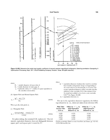
Figure 10-53D. Determine the inside heat transfer coefficient of several common vapor/liquid refrigerants. (Used by permission: Ganapathy, V.
Hydrocarbon Processing, Sept. 1977. ©Gulf Publishing Company, Houston, Texas. All rights reserved.)
where
where
d e equivalent diameter of plain tube (used to correlate
D 1 outside diameter of inner tube, ft
heat transfer and pressure drop) corresponding to
D 2 inside diameter of outer pipe, ft
the metal volume of a finned tube, in. It is the volu-
r h hydraulic radius, ft (radius of a pipe equivalent to
metric equivalent diameter of the root tube plus the
the annulus cross-section)
addition to the root-tube O.D. if the volume of the
fin metal were added to it to form a new root-tube
(b) Square Pitch and Rotated Square Pitch O.D. 206 See Figure 10-10H.
d e equivalent diameter, in.
2
2
4p 1d e ¿2 >4
d e (10-63)
d e ¿ For use in the equivalent diameter equations, the follow-
ing volumetric d e , in., values are taken from reference 206.
Where p is the tube pitch, in.
1
Plain Tube 19fins/in. / 16 in. 16fins/in. / 16 in.
1
(c) Triangular Pitch Section Tube High Equivalent High Equivalent
O.D. in. Diameter d e , in. Diameter d e ,in.
2
430.5p10.86p2 0.5 1d e ¿2 >4
d e (10-64) 0.625 0.535 0.540
0.5 d e ¿ 0.750 0.660 0.665
0.875 0.785 0.790
For plain tubing, the nominal O.D. replaces d e . The vol- 1.000 0.910 0.917
umetric equivalent diameter does not distinguish between Used by permission: Based on data from Kern and Kraus, pp. 512—513,
square pitch and square pitch rotated by 45°. ©1972. McGraw-Hill, Inc.