
Page 143 - Applied Process Design For Chemical And Petrochemical Plants Volume III
P. 143
66131_Ludwig_CH10D 5/30/2001 4:30 PM Page 107
Heat Transfer 107
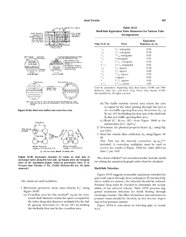
Table 10-21
Shell-Side Equivalent Tube Diameters for Various Tube
Arrangements
Equivalent
Tube O.D. In. Pitch Diameter, d e , In.
1 5 / 8 triangular 0.36
/ 2
1 3 / 4 triangular 0.74
/ 2
3 15 / 16 triangular 0.55
/ 4
3 1 triangular 0.73
/ 4
1
1 1 / 4 triangular 0.72
1 9
1 / 4 1 / 16 triangular 0.91
1 5 / 8 square 0.48
/ 2
1 3 / 4 square 0.88
/ 2
3 15 / 16 square 0.72
/ 4
3 1 square 0.95
/ 4
1
1 1 / 4 square 0.99
1 9
1 / 4 1 / 16 square 1.23
Used by permission: Engineering Data Book Section, ©1960 and 1984.
Wolverine Tube Inc.; and Kern, D.Q. Process Heat Transfer, ©1950.
McGraw-Hill Inc. All rights reserved.
(b) The baffle window cut-out area minus the area
occupied by the tubes passing through this area is
Figure 10-55. Shell-side baffles and cross-flow area. the net baffle opening flow area. Determine G b , as
2
lb/sec (ft ) by dividing the flow rate of the shell side
by this new baffle opening flow area.
2
(c) Read G e , lb/sec (ft ), from Figure 10-60 at the
intersection of G c and G b .
2. Determine the physical property factor, p , using Fig-
ure 10-61.
3. Read the outside film coefficient, h o , using Figure 10-
62.
Note: This has the viscosity correction ( / w ) 0.14 ,
included. A correction multiplier must be used to
correct the results of Figure 10-62 for tubes different
5
than / 8 -in. O.D.
Figure 10-56. Equivalent diameter for tubes on shell side of The charts of Rubin are somewhat similar and also useful
98
exchanger taken along the tube axis. (a) Square pitch, (b) triangular
pitch on 60° equilateral angles. (Used by permission: Kern, D. Q. for solving the equation by graph rather than by calculator.
Process Heat Transfer, 1 Ed., ©1959. McGraw-Hill, Inc. All rights
st
reserved.) Shell-Side Velocities
Figure 10-63 suggests reasonable maximum velocities for
gases and vapors through heat exchangers. If entrained liq-
The charts are used as follows: uid or solids are present, the velocities should be reduced.
Pressure drop must be checked to determine the accept-
1. Determine geometric mean mass velocity, G e , using ability of any selected velocity. Table 10-22 presents sug-
Figure 10-60. gested maximum velocities for fluids flowing through
38
(a) Cross-flow area for this method equals the hori- exchanger nozzles. The effect of entrance and exit losses on
zontal shell diameter minus the space occupied by pressure losses should be checked, as they become impor-
the tubes along this diameter, multiplied by the baf- tant in low pressure systems.
2
fle spacing. Determine G c , lb/sec (ft ) by dividing Figure 10-64 is convenient in selecting pipe or nozzle
the shell-side flow rate by the cross-flow area. sizes.