
Page 147 - Applied Process Design For Chemical And Petrochemical Plants Volume III
P. 147
66131_Ludwig_CH10D 5/30/2001 4:30 PM Page 111
Heat Transfer 111
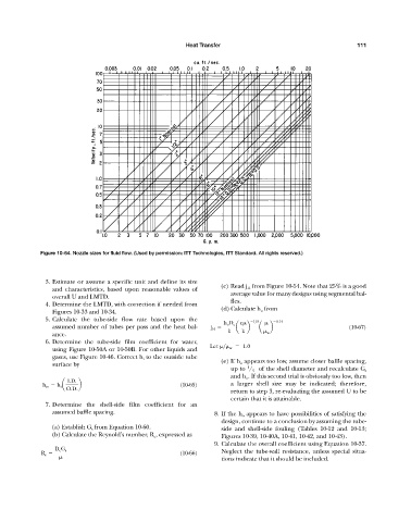
Figure 10-64. Nozzle sizes for fluid flow. (Used by permission: ITT Technologies, ITT Standard. All rights reserved.)
3. Estimate or assume a specific unit and define its size
(c) Read j H from Figure 10-54. Note that 25% is a good
and characteristics, based upon reasonable values of
average value for many designs using segmental baf-
overall U and LMTD.
fles.
4. Determine the LMTD, with correction if needed from
(d) Calculate h o from
Figures 10-33 and 10-34.
5. Calculate the tube-side flow rate based upon the
h o D e c 1>3 0.14
assumed number of tubes per pass and the heat bal- j H a b a b (10-67)
k k w
ance.
6. Determine the tube-side film coefficient for water,
Let > w 1.0
using Figure 10-50A or 10-50B. For other liquids and
gases, use Figure 10-46. Correct h i to the outside tube
(e) If h o appears too low, assume closer baffle spacing,
surface by
1
up to / 5 of the shell diameter and recalculate G s
and h o . If this second trial is obviously too low, then
I.D.
h io h i a b (10-65) a larger shell size may be indicated; therefore,
O.D.
return to step 3, re-evaluating the assumed U to be
certain that it is attainable.
7. Determine the shell-side film coefficient for an
assumed baffle spacing. 8. If the h o appears to have possibilities of satisfying the
design, continue to a conclusion by assuming the tube-
(a) Establish G s from Equation 10-60. side and shell-side fouling (Tables 10-12 and 10-13;
(b) Calculate the Reynold’s number, R e , expressed as Figures 10-39, 10-40A, 10-41, 10-42, and 10-43).
9. Calculate the overall coefficient using Equation 10-37.
D e G s
R e (10-66) Neglect the tube-wall resistance, unless special situa-
tions indicate that it should be included.