
Page 145 - Applied Process Design For Chemical And Petrochemical Plants Volume III
P. 145
66131_Ludwig_CH10D 5/30/2001 4:30 PM Page 109
Heat Transfer 109
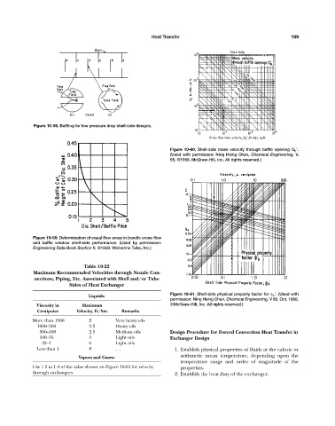
Figure 10-58. Baffling for low pressure drop shell-side designs.
Figure 10-60. Shell-side mass velocity through baffle opening G b .
(Used with permission: Ning Hsing Chen, Chemical Engineering, V.
65, ©1958. McGraw-Hill, Inc. All rights reserved.)
Figure 10-59. Determination of equal flow areas in bundle cross-flow
and baffle window shell-side performance. (Used by permission:
Engineering Data Book Section II, ©1959. Wolverine Tube, Inc.)
Table 10-22
Maximum Recommended Velocities through Nozzle Con-
nections, Piping, Etc. Associated with Shell and/or Tube
Sides of Heat Exchanger
Figure 10-61. Shell-side physical property factor for p . (Used with
Liquids:
permission: Ning Hsing Chen, Chemical Engineering, V 65, Oct. 1958.
Viscosity in Maximum ©McGraw-Hill, Inc. All rights reserved.)
Centipoise Velocity, Ft/Sec Remarks
More than 1500 2 Very heavy oils
1000—5000 2.5 Heavy oils
500—100 2.5 Medium oils Design Procedure for Forced Convection Heat Transfer in
100—350 5 Light oils Exchanger Design
35—10 6 Light oils
Less than 1 8 . . . 1. Establish physical properties of fluids at the caloric or
arithmetic mean temperature, depending upon the
Vapors and Gases:
temperature range and order of magnitude of the
Use 1.2 to 1.4 of the value shown on Figure 10-63 for velocity properties.
through exchangers.
2. Establish the heat duty of the exchanger.