Page 138 - Applied Process Design For Chemical And Petrochemical Plants Volume III
P. 138

66131_Ludwig_CH10D  5/30/2001 4:30 PM  Page 103


                                                                    Heat Transfer                                          103


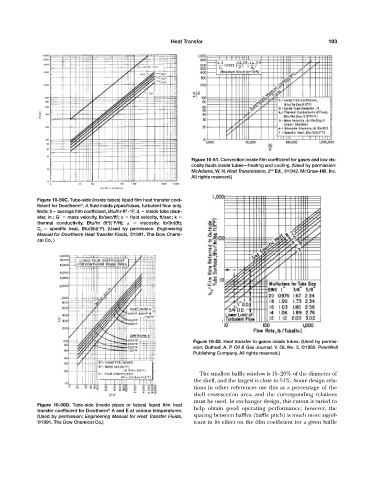
                                                                           Figure 10-51. Convection inside film coefficient for gases and low vis-
                                                                           cosity fluids inside tubes—heating and cooling. (Used by permission:
                                                                                                      nd
                                                                           McAdams, W. H. Heat Transmission, 2 Ed., ©1942. McGraw-Hill, Inc.
                                                                           All rights reserved.)


                     Figure 10-50C. Tube-side (inside tubes) liquid film heat transfer coef-
                                    ®
                     ficient for Dowtherm . A fluid inside pipes/tubes, turbulent flow only.
                          –
                                                    2
                     Note: h  average film coefficient, Btu/hr-ft -°F; d i   inside tube diam-
                     eter, in.; G    mass velocity, lb/sec/ft ; v   fluid velocity, ft/sec; k
                                                 2
                     thermal conductivity, Btu/hr (ft )(°F/ft);     viscosity, lb/(hr)(ft);
                                              2
                     C p    specific heat, Btu/(lb)(°F). (Used by permission: Engineering
                     Manual for Dowtherm Heat Transfer Fluids, ©1991. The Dow Chemi-
                     cal Co. )


                                                                            Figure 10-52. Heat transfer to gases inside tubes. (Used by permis-
                                                                            sion: Buthod, A. P. Oil & Gas Journal, V. 58, No. 3, ©1960. PennWell
                                                                            Publishing Company. All rights reserved.)


                                                                              The smallest baffle window is 15—20% of the diameter of
                                                                            the shell, and the largest is close to 51%. Some design rela-
                                                                            tions in other references use this as a percentage of the
                                                                            shell cross-section area, and the corresponding relations
                                                                            must be used. In exchanger design, this cutout is varied to
                     Figure 10-50D.  Tube-side (inside pipes or tubes) liquid film heat
                     transfer coefficient for Dowtherm A and E at various temperatures.  help obtain good operating performance; however, the
                                              ®
                     (Used by permission: Engineering Manual for Heat Transfer Fluids,  spacing between baffles (baffle pitch) is much more signif-
                     ©1991. The Dow Chemical Co.)                           icant in its effect on the film coefficient for a given baffle
   133   134   135   136   137   138   139   140   141   142   143