
Page 134 - Applied Process Design For Chemical And Petrochemical Plants Volume III
P. 134
66131_Ludwig_CH10D 5/30/2001 4:30 PM Page 99
Heat Transfer 99
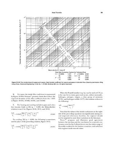
Btu/hr-ft 2 -°F Tubeside heat transfer coefficient, corrected for viscosity, h i
Mass velocity G , lb/sec-ft 2
Tube Size Correction Factors for Turbulent Flow
3 / 4 " × 14 BWG 1.011 1" × 14 BWG 0.942
16 1.000 1 / 4 " ×10 0.912
1
1" × 10 0.967 12 0.903
12 0.955 14 0.894
Figure 10-48. Flow inside tubes for gases and vapors. Heat transfer coefficient for vapors and gases in turbulent flow. (Used by permission: Ning
Hsing Chen, Chemical Engineering, V. 66, No. 1, ©1959. McGraw-Hill, Inc. All rights reserved.)
When the Prandtl number (c /k a ) can be used at 0.74, as
D. For water, the inside film coefficient is represented is the case for so many gases such as air, carbon monoxide,
49
by Figure 10-50A. Furman presents charts that reduce the hydrogen, nitrogen, oxygen, a close group of ammonia
expected deviation of the film coefficient from the
20% (0.78), and hydrogen sulfide (0.77), this relation reduces to
of Figure 10-50A, 10-50B, 10-50C, and 10-50D. the following:
E. For heating and cooling turbulent gases and other h i D DGC 0.8
low viscosity fluids at DG/ 8,000; the Dittus-Boelter 0.026a b (10-50)
k a k a
relation is used. See Figures 10-46, 10-51, and 10-52.
Note that the values of the initial coefficients on the right-
h i D DG 0.8 c 0.4 0.14
0.0243a b a b a b (10-48) side of the preceding equations vary significantly among sev-
k a k a w eral respected references; therefore, the engineer should
not be surprised to note these variations in the literature.
For cooling, DG/ 8,000, the following is sometimes Pierce 164 proposes and illustrates good agreement
used in place of the preceding relation, Figure 10-51: between the test data and the correlation for a smooth con-
tinuous curve for the Colburn factor over the entire range of
h i D DG 0.8 c 0.4 0.14
0.023a b a b a b (10-49) Reynolds numbers for the laminar, transition, and turbulent
k a k a w flow regimes inside smooth tubes: