
Page 136 - Applied Process Design For Chemical And Petrochemical Plants Volume III
P. 136
66131_Ludwig_CH10D 5/30/2001 4:30 PM Page 101
Heat Transfer 101
Liquids in turbulent flow in circular helical coils 80, 81
should be handled the same as for gases or use 1.2 h 1 for
straight tubes.
Film Coefficients with Fluids Outside Tubes
Forced Convection
Film coefficients for turbulent flow that exist on the out-
side or shell side of the conventional baffled shell and tube
exchanger are correlated for hydrocarbons, organic com-
pounds, water, aqueous solutions, and gases 5, 70 by
0.55 1>3 0.14
h o D e D e G s c
0.36 a b a b a b (10-55)
k a k a w
and as represented in Figure 10-54, deviation: 0 to 20 per-
cent. The G s is correlated for both cross- and parallel-flow
through the bundle by using the hydraulic radius along the
70
tubes only. Figure 10-55 is helpful in visualizing shell-side
fluid flow.
where
h o film coefficient outside of tubes in bundle, Btu/hr
2
(ft )(°F)
2
k a thermal conductivity, Btu/hr (ft ) (°F/ft)
2
G s mass rate, lb/hr (ft )
D e equivalent tube diameter, ft
d e equivalent tube diameter, in.
a s flow area across the tube bundle, ft 2
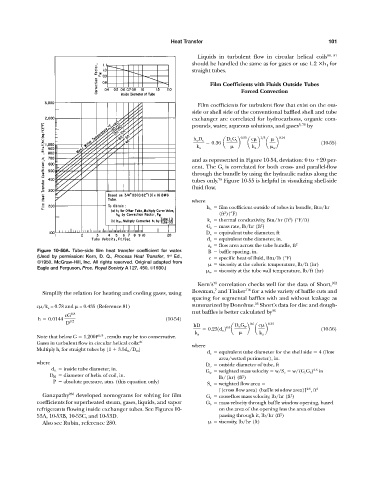
Figure 10-50A. Tube-side film heat transfer coefficient for water. B baffle spacing, in.
st
(Used by permission: Kern, D. Q., Process Heat Transfer, 1 Ed., c specific heat of fluid, Btu/lb (°F)
©1950. McGraw-Hill, Inc. All rights reserved. Original adapted from viscosity at the caloric temperature, lb/ft (hr)
Eagle and Ferguson, Proc. Royal Society A 127, 450, ©1930.)
w viscosity at the tube wall temperature, lb/ft (hr)
70
Kern’s correlation checks well for the data of Short, 102
7
Simplify the relation for heating and cooling gases, using Bowman, and Tinker 116 for a wide variety of baffle cuts and
spacing for segmental baffles with and without leakage as
36
c /k a = 0.78 and = 0.435 (Reference 81) summarized by Donohue. Short’s data for disc and dough-
nut baffles is better calculated by 36
cG 0.8
h 0.0144 (10-54)
D 0.2 0.6 0.33
hD 0.6 D o G w c
0.231d e 2 a b a b (10-56)
k a k a
Note that below G 1,200P 2/3 , results may be too conservative.
Gases in turbulent flow in circular helical coils: 81
where
Multiply h i for straight tubes by [1 3.5d it /D H ]
d e equivalent tube diameter for the shell side 4 (flow
area/wetted perimeter), in.
where
D o outside diameter of tube, ft
d it inside tube diameter, in. 0.5
G w weighted mass velocity w/S e w/(G c G b ) in
D H diameter of helix of coil, in. 2
lb/(hr) (ft )
P absolute pressure, atm. (this equation only)
S e weighted flow area
0.5
[(cross flow area) (baffle window area)] , ft 2
Ganapathy 263 developed nomograms for solving for film G c cross-flow mass velocity, lb/hr (ft )
2
coefficients for superheated steam, gases, liquids, and vapor G b mass velocity through baffle window opening, based
refrigerants flowing inside exchanger tubes. See Figures 10- on the area of the opening less the area of tubes
2
53A, 10-53B, 10-53C, and 10-53D. passing through it, lb/hr (ft )
Also see Rubin, reference 280. viscosity, lb/hr (ft)