
Page 137 - Applied Process Design For Chemical And Petrochemical Plants Volume III
P. 137
66131_Ludwig_CH10D 5/30/2001 4:30 PM Page 102
102 Applied Process Design for Chemical and Petrochemical Plants
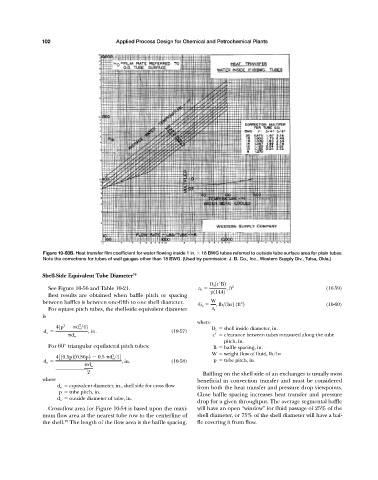
Figure 10-50B. Heat transfer film coefficient for water flowing inside 1 in. 18 BWG tubes referred to outside tube surface area for plain tubes.
Note the corrections for tubes of wall gauges other than 18 BWG. (Used by permission: J. B. Co., Inc., Western Supply Div., Tulsa, Okla.)
Shell-Side Equivalent Tube Diameter 70
D s 1c¿B2
See Figure 10-56 and Table 10-21. a s , ft 2 (10-59)
p11442
Best results are obtained when baffle pitch or spacing
between baffles is between one-fifth to one shell diameter. G s W , lb>1hr2 1ft 2 (10-60)
2
For square pitch tubes, the shell-side equivalent diameter a s
is
where
2
2
41p d o >42 D s shell inside diameter, in.
d e , in. (10-57)
d o c clearance between tubes measured along the tube
pitch, in.
For 60° triangular equilateral pitch tubes: B baffle spacing, in.
W weight flow of fluid, lb/hr
2
4310.5p210.86p2 0.5 d o >44
d e , in. (10-58) p tube pitch, in.
d o
2 Baffling on the shell side of an exchanger is usually most
where beneficial in convection transfer and must be considered
d e equivalent diameter, in., shell side for cross flow
from both the heat transfer and pressure drop viewpoints.
p tube pitch, in.
Close baffle spacing increases heat transfer and pressure
d o outside diameter of tube, in.
drop for a given throughput. The average segmental baffle
Cross-flow area for Figure 10-54 is based upon the maxi- will have an open “window” for fluid passage of 25% of the
mum flow area at the nearest tube row to the centerline of shell diameter, or 75% of the shell diameter will have a baf-
70
the shell. The length of the flow area is the baffle spacing. fle covering it from flow.