
Page 176 - Applied Process Design For Chemical And Petrochemical Plants Volume III
P. 176
66131_Ludwig_CH10E 5/30/2001 4:33 PM Page 139
Heat Transfer 139
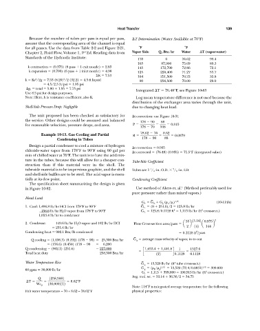
Because the number of tubes per pass is equal per pass, T Determination (Water Available at 70°F)
assume that the corresponding area of the channel is equal
for all passes. Use the data from Table 2-2 and Figure 2-21, °F °F
rd
Chapter 2, Fluid Flow, Volume 1, 3 Ed. Reading data from Vapor Side Q, Btu/hr Water T (vapor-water)
Standards of the Hydraulic Institute:
178 0 78.62 99.4
165 87,900 75.69 89.3
k contraction (0.375) (6 pass 1 exit nozzle) 2.63 145 172,700 72.86 72.1
k expansion (0.700) (6 pass 1 inlet nozzle) 4.90 125 220,400 71.27 53.7
K 7.53 104 251,500 70.23 33.8
2
2
k Kv /2g 7.53 (6.20) /2 (32.2) 4.5 ft liquid 90 258,500 70.00 20.0
4.5/2.3 ft/psi 1.95 psi
p t total 5.80 1.95 7.75 psi
Integrated T 76.48°F, see Figure 10-83
Use 8.5 psi for design purposes.
Note: Here, k is resistance coefficient, also K. Log mean temperature difference is not used because the
distribution of the exchanger area varies through the unit,
Shell-Side Pressure Drop: Negligible due to changing heat load.
The unit proposed has been checked as satisfactory for t correction: use Figure 10-34
the service. Other designs could be assumed and balanced 178 90 88
for reasonable velocities, pressure drops, and area. P 0.815
178 70 108
78.62 70 8.62
Example 10-13. Gas Cooling and Partial R 0.0979
Condensing in Tubes 178 90 88
Design a partial condenser to cool a mixture of hydrogen
t correction 0.935
chloride-water vapor from 178°F to 90°F using 60 gal per
t corrected (76.48) (0.935) 71.5°F (integrated value)
min of chilled water at 70°F. The unit is to have the acid mix-
ture in the tubes, because this will allow for a cheaper con-
Tube-Side Coefficient
struction than if this material were in the shell. The
tube-side material is to be impervious graphite, and the shell Tubes are 1 / 4 -in. O.D. / 8 -in. I.D.
1
7
and shell-side baffles are to be steel. The acid vapor is essen-
tially at its dew point. Condensing Coefficient
The specification sheet summarizing the design is given
1
in Figure 10-82. Use method of Akers et. al. (Method preferably used for
pure pressure rather than mixed vapors.)
Head Load –
G e G L G g ( L / v ) 1/2 (10-114A)
–
1. Cool: 1,496.8 lb/hr HCI from 178°F to 90°F G L (0 251.6)/2 125.8 lb/hr
–
2
2
156.6 lb/hr H 2 O vapor from 178°F to 90°F G L 125.8/0.1128 ft 1,115 lb/hr (ft cross-sect.)
1,653.4 lb/hr to condenser
55 13.142 0.875 2
2. Condense: 149.6 lb/hr H 2 O vapor and 102 lb/hr HCI Flow Cross-section area>pass a b a b
251.6 lb/hr 2 142 144
2
Condensing heat 902.1 Btu/lb condensed 0.1128 ft >pass
–
Q cooling (1,496.3) (0.192) (178 90) 25,300 Btu/hr G g average mass velocity of vapor, in to out
(156.6) (0.450) (178 90 6,200
Q condensing (902.1) (251.6) 227,000 1,653.4 1,401.8 1 1527.6
c d
Total heat duty 258,500 Btu/hr 122 0.1128 0.1128
–
Water Temperature Rise G g 13,520 lb/hr (ft tube cross-sect.)
2
–
G g ( L / g ) 1/2 13,520 (72.4/0.0831) 1/2 399.800
60 gpm 30,000 lb/hr
2
G e 1,115 399,800 400,915 lb/hr (ft cross-sect.)
Avg. mol. wt. 33.14 36.36/2 34.75
Q 1258,5002
T 8.62°F
130,0002112
Wc p
Note: 114°F is integrated average temperature for the following
Exit water temperature = 70 + 8.62 = 78.62°F physical properties: