
Page 180 - Applied Process Design For Chemical And Petrochemical Plants Volume III
P. 180
66131_Ludwig_CH10E 5/30/2001 4:33 PM Page 143
Heat Transfer 143
Condensing Vapors in Presence of Noncondensable Gases nitrogen. The following is a reasonable short-cut approach
that can be acceptable for many applications but certainly is
A stream containing a noncondensable and vapors to be not as accurate as the Colburn-Hougen 30, 31 method:
condensed must be considered so that the continually 1
H (10-115A)
changing gas vapor physical properties (and some thermal 1 Cy
properties), gas film heat transfer coefficient, and mass gas
flow rate are adequately represented. This operation is usu- where
ally a constant pressure process. The vapor condenses at its
H heat transfer coefficient ratio, h M /h Nu
dew-point on the tubes, thereby providing a wet surface; a h M effective heat transfer film coefficient, Btu/hr-ft -°F
2
noncondensable gas film surrounds this surface; and the h Nu condensing film coefficient by Nusselt equation
2
vapor of the stream diffusing through this film condenses Btu/hr-ft -°F
into the liquid film of the condensate on the tube, see Fig- y mol (volume) percent noncondensable gas in bulk
ure 10-84. The sensible heat and latent heat of the vapor stream. 62
are transferred through the gas film and the liquid film to C see following table
the tube surface (except when considerable subcooled
condensate film exists, in which cases there may be con-
densation or fogging in the gas film). The rigorous
30
method of design of Colburn and Colburn and Hougen 31
involving trial-and-error calculations is considered the
most accurate of the various alternate procedures pub-
70
lished to date. Kern presents a very useful analysis of spe-
cial design problems with examples.
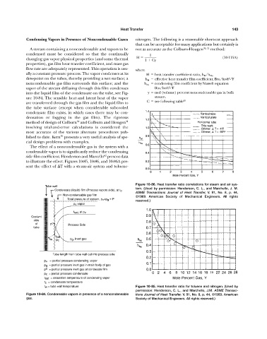
The effect of a noncondensable gas in the system with a
condensable vapor is to significantly reduce the condensing
62
side film coefficient. Henderson and Marcello present data
to illustrate the effect. Figures 10-85, 10-86, and 10-86A pre-
sent the effect of T with a steam-air system and toluene-
Figure 10-86. Heat transfer ratio correlations for steam and air sys-
Tube wall
tem. (Used by permission: Henderson, C. L., and Marchello, J. M.
Condensate (liquid) film (Process vapors side), at t c
ASME Transactions Journal of Heat Transfer, V. 91, No. 8, p. 44,
Non-condensable gas film
©1969. American Society of Mechanical Engineers. All rights
Total pressure of system, p v +p g = P
reserved.)
p v vapor
t sat. at p v
Coolant
side
of p o Process Side
tube
t sat
t w p g , Inert gas
p c
Tube length from tube wall out into process side
p v = partial pressure condensing. vapor
p g = partial pressure inert gas in main body of gas
p o = partial pressure inert gas at condesate film
p c = partial pressure condensate
t sat = saturation temperature of condensing vapor
t c = condensate temperature
t w = tube wall temperature Figure 10-85. Heat transfer ratio for toluene and nitrogen. (Used by
permission: Henderson, C. L., and Marchello, J.M. ASME Transac-
Figure 10-84. Condensable vapors in presence of a noncondensable tions Journal of Heat Transfer, V. 91, No. 8, p. 44, ©1969. American
gas. Society of Mechanical Engineers. All rights reserved.)