
Page 183 - Applied Process Design For Chemical And Petrochemical Plants Volume III
P. 183
66131_Ludwig_CH10E 5/30/2001 4:33 PM Page 146
146 Applied Process Design for Chemical and Petrochemical Plants
70
number of increments, 5—7, will produce results on the high The general method as outlined by Kern has been sup-
side. In one case studied the use of 6 points compared to 17 plemented in the following discussion. The test of Revilock 96
points resulted in an area 36% too high. An important fac- indicates the general applicability of the method.
tor in this analysis is the shape of the heat transfer curve.
Increments should be chosen smaller in the areas where the 1. The method is applicable only to gas-vapor mixtures
rate of change of heat load with temperature is the greatest with the vapor at saturation. However, systems involving
(see Figures 10-87 and 10-88). superheated mixtures and subcooling can be handled
39
The work of Dmytryszyn indicates that the best agree- as separate problems and added to the cooler-
ment between actual and calculated surface areas using the condenser area requirements to form a complete unit.
Colburn-Hougen method, when tested with vapors outside a 2. Assume temperature increments of condensation from
single vertical tube, requires a graphical solution to calculate the inlet temperature to the outlet. The increments
the heat transfer surface required to cool the incoming gas should be smaller near the inlet as most of this heat
mixture to its dew point (area described 1, 2, 3, 4), Figure load will be transferred at the higher temperature level.
10-89. The area (described as 1, 2, 3, 5, l) calculated for gas The number of increments is a function of the desired
desuperheating is too large when determined by the usual accuracy. However, as a rule, the minimum should be 4,
equations; likewise, calculations based on an overall con- with 6 or more being preferred.
densing coefficient give results that are too low. 39 3. Calculate the gas cooling and condensing heat loads
for each increment separately and plot a curve repre-
senting the total heat load versus temperature.
4. Assume an exchanger unit, establishing shell size, num-
ber of tubes, and number of passes. Because the esti-
mation of overall U values for this type of unit is much
more variable than for some of the other units, a rough
2
value may be taken between 30 and 60 Btu/hr (ft ) (°F)
as a start (see Table 10-15). The actual weighted t will
be somewhat larger than an LMTD value; however, this
is difficult to approximate without a trial or two or
unless a condensate film temperature, t f , can be esti-
mated for the inlet and outlet conditions of several
intervals. An average difference value of these t f values
and the inlet gas temperature to the interval will give a
reasonable estimating value for the temperature differ-
ence in determining the estimating area, A.
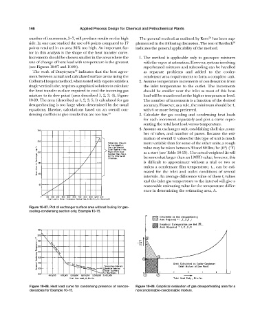
Figure 10-87. Plot of exchanger surface area without fouling for gas-
cooling-condensing section only, Example 10-15.
Figure 10-88. Heat load curve for condensing presence of noncon- Figure 10-89. Graphical evaluation of gas desuperheating area for a
densables for Example 10-15. noncondensable-condensable mixture.