
Page 174 - Applied Process Design For Chemical And Petrochemical Plants Volume III
P. 174
66131_Ludwig_CH10E 5/30/2001 4:33 PM Page 137
Heat Transfer 137
Area available for gas cooling (5 ft) (0.196) (646) 632 ft 2
Area calculated required for gas cooling 494 ft
632 494
Percent extra area 11002 28%
494
Area available for condensing (10.5 ft) (0.196) (646) 1330 ft 2
Area calculated required for condensing 1220 ft 2
(A) 1,330 1,220
Percent extra area 11002 9%
1,220
The baffling for the gas cooling area could be adjusted to
make more area available for condensing and, thereby, bal-
ance the unit a little better. In operation these areas will
become balanced, and some condensing will undoubtedly
take place in the gas cooling area. In either case the unit size
is within the range to allow reasonable plant operating flex-
ibility without increasing the capital cost of the unit signifi-
(B) cantly.
For the tube side pressure drop, refer to Figure 10-138:
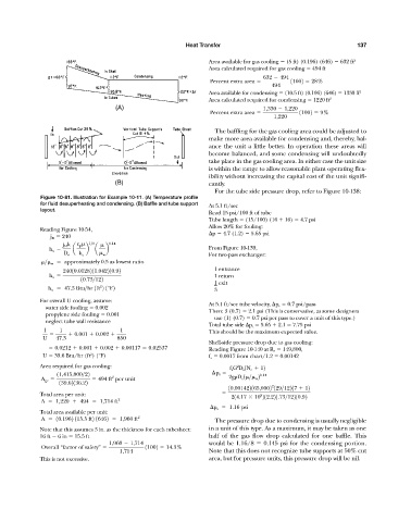
Figure 10-81. Illustration for Example 10-11. (A) Temperature profile
for fluid desuperheating and condensing. (B) Baffle and tube support At 5.1 ft/sec
layout.
Read 15 psi/100 ft of tube
Tube length (15/100) (16 16) 4.7 psi
Allow 20% for fouling:
Reading Figure 10-54,
p 4.7 (1.2) 5.65 psi
j H 240
j H k c p 1>3 0.14
h o a b a b From Figure 10-139,
D e k a w For two-pass exchanger:
> w approximately 0.5 as lowest ratio
1 entrance
24010.0128211.042210.92
h o 1 return
10.73>122
1 exit
2
h o 47.3 Btu>hr 1ft 2 1°F2 3
For overall U cooling, assume:
At 5.1 ft/sec tube velocity, p r 0.7 psi/pass
water side fouling 0.002
Then: 3 (0.7) 2.1 psi (This is conservative, as some designers
propylene side fouling 0.001
use (1) (0.7) 0.7 psi per pass to cover a unit of this type.)
neglect tube wall resistance
Total tube side p t 5.65 2.1 7.75 psi
1 1 1 This should be the maximum expected value.
0.001 0.002
U 47.3 850
Shell-side pressure drop due to gas cooling:
0.0212 0.001 0.002 0.00117 0.02537 Reading Figure 10-140 at R e 149,800,
U 39.6 Btu/hr (ft ) (°F) f a 0.0017 from chart/1.2 0.00142
2
Area required for gas cooling: 2
f s G D s 1N c 12
p s
11,415,000>22 0.14
2
A gc 494 ft per unit 2g D e 1 > w 2
139.62136.22
2
10.001422165,0002 129>12217 12
Total area per unit: 214.17 10 212.221.73>12210.92
8
A 1,220 494 1,714 ft 2
p s 1.16 psi
Total area available per unit:
A 10.1962 115.5 ft2 16462 1,960 ft 2 The pressure drop due to condensing is usually negligible
Note that this assumes 3 in. as the thickness for each tubesheet: in a unit of this type. As a maximum, it may be taken as one
16 ft 6 in 15.5 ft half of the gas flow drop calculated for one baffle. This
1,960 1,714 would be 1.16/8 0.145 psi for the condensing portion.
Overall “factor of safety” 11002 14.3%
1,714 Note that this does not recognize tube supports at 50% cut
This is not excessive. area, but for pressure units, this pressure drop will be nil.